Driving the field of LPEM forward at the Gordon conference

Driving the field of LPEM forward at the Gordon conference

Last month, our Stream Product Manager Gin Pivak, CTO Hugo Perez and Microsystems Engineer Tijn van Omme visited the Gordon Research Conference (GRC) on Liquid Phase Electron Microscopy (LPEM). They were there to inform the LPEM community about our Stream system which allows researchers to introduce an accurate and controlled liquid environment combined with in-situ heating or biasing possibilities.
We realized that most researchers were still assuming that all liquid holders for LPEM are still relying on the ‘bathtub’ style (i.e. pocket structure where the 2 chips are placed). This is far from ideal, as the liquid bypasses the nano-cell and it only flows towards the window by diffusion in a non-controlled and spontaneous way. Therefore, it was a big relief for the LPEM community to learn that our Stream system now enables the real benefits, like (a) accurately controlling pressure and flow over the window, (b) controlling membrane bulging (i.e. controlling the liquid thickness) to enable higher resolutions, (c) enabling meaningful results in structure determination and analytical microscopy studies (e.g. EDS, EELS, electron diffraction), (d) controlling and mitigating bubble formation and most importantly, (e) reproducible experiments.
The Gordon Research Conferences are a special type of conference aimed at advancing frontier research. The idea is to bring all the relevant people in the field together to discuss and present (unpublished) results and to talk about the future directions of the field. All the major players in the field were present, and there was a lot of time for interaction. This created an open atmosphere, in which knowledge was shared and collaborations were established.
It became clear that the Liquid Phase Electron Microscopy community is maturing. LPEM offers a unique way for scientists to obtain information within a wide range of fields, including nanoparticle synthesis, self-assembly, corrosion, batteries, semicon, proteins and cells. However, compared to Cryo-EM, the field is still in its early days. A number of challenges still exist before results will be reproducibly accepted by non-microscopist communities. For example how to deal with the influence of the e-beam and how to control other influencing parameters.

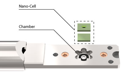
‘Bathtub’ style LPEM system. Liquid bypasses the Nano-Cell and flows toward the window in a non-controlled and spontaneous way.

DENSsolutions Stream LPEM system. On-chip microfluidic channel enables full control over the liquid flow and pressure, thus the liquid-sample interaction.

On the first day of the conference, our CTO gave a presentation about the Stream Liquid Biasing and Liquid Heating system which resonated well amongst the attendees. The on-chip microfluidic channel in combination with the pressure control in the Stream system aligns well with the current and future demands of the field, as it enables control over the flow and liquid layer thickness.

Thank you for reading

To learn more about our LPEM system:

Do you want to receive great articles like this in your mailbox? Subscribe to our newsletter.

Our partnership with the EPSRC/Jeol Centre for Liquid Phase Electron Microscopy at UCL, London

Our partnership with the EPSRC/Jeol Centre for Liquid Phase Electron Microscopy at UCL, London

DENSsolutions LPEM systems enable advances in Life Science

Dr. Lorena Ruiz-Perez (left) and Prof. Guiseppe Battaglia (right)

On the 12th of November, DENSsolutions in cooperation with UCL and Quantum Design UK will be holding a Stream workshop at the EPRSC/Jeol Centre for Liquid Phase Electron Microscopy (LPEM) facility at UCL, London. At the LPEM facility, opened in 2017, Dr. Lorena Ruiz-Perez uses the DENSsolutions Liquid In Situ solutions to characterise soft organic nanomaterials via TEM imaging. In this article, we take a look at the LPEM research that Ruiz-Perez is doing within the Molecular Bionics lab.

Molecular Bionics

The goal of the group is to mimic specific biological functions and/or introduce operations that do not exist in nature by engineering bionic units made of polymers. This goal is achieved by a multidisciplinary team of chemists, physicists, mathematicians, engineers and biologists.

The LTEM team at the Molecular Bionics group is formed by Prof. Guiseppe Battaglia, director of the facility, Dr. Lorena Ruiz-Perez, manager of the facility. Cesare de Pace and Gabriele Marchello are PhD students involved in the experimental development of LTEM and LTEM image analysis respectively.

Inside the group, Dr. Lorena Ruiz-Perez has been using the DENSsolutions Ocean system to work mainly on two different projects.

Polymer assemblies

For the first project, she has been using the system to investigate soft matter polymer assemblies. As we have shown in one of our earlier articles, these assemblies have the potential to be used for targeted drug delivery inside the human body. These kinds of assemblies have been well studied using Cryogenic electron microscopy (cryo-EM). One of the main advantages of employing LPEM is that it allows us to gain new insights into the dynamic behaviour of these assemblies within a liquid that were not possible using images of the vitrified, i.e. frozen sample. In liquid, you can observe for instance the fluctuation of the polymer assembly membranes and hence investigate significant mechanical properties of the soft materials.

Proteins dynamic behaviour

Their second project involves investigating the dynamic behaviour of proteins in liquid. These proteins move by the so-called ‘Brownian motion’. The group wants to understand the structure of the proteins inside their native environment. While the protein is moving in water, they can capture many different profiles in order to reconstruct a 3D image of the protein structure. There is a minimum frame amount needed for the reconstruction, so the time component becomes fundamental in these in-situ studies. The investigation aims to create a library of proteins, like the RCSB PDB, with information on dynamic processes which can complement the information already supplied by the well established cryo-EM technique. Their first results, studying ferritin proteins, were presented at Manchester 2019*.

Schematic representation showing the temporal evolution of the density map reconstruction process of ferritin. A five second long video was segmented into five one second long sub-videos The brownian particle analysis algorithm extracted about 1000 particle profiles from each sub-video, generating five different density maps. The quality and resolution of the refined density maps resulted in being inversely proportional to the sample exposure time to the electron beam.

Proteins play a pivotal role in our physiological conditions and associated diseases. A deeper understanding of the kinetics governing the mechanistic behaviour of proteins in liquid media can lead to big improvements in drug design and ultimately in general healthcare.

*This manuscript is currently being updated with long molecular dynamics simulations of ferritin in solution.

The new Stream system

Now the group is advancing to the DENSsolutions Stream system, allowing them to do new kinds of experiments. The big advantage of the Stream system is that it can control the bulging of the viewing windows and therefore the liquid thickness. Controlling the bulging is essential for creating reproducible results. In previous LPEM in situ systems, the window bulging could differ between experiments, thus preventing experiment reproducibility.

Now with the Stream system, the bulging can be adjusted precisely for each new experiment, guaranteeing the same level of bulging and, therefore, consistent results. Controlling the liquid thickness is also important to achieve high contrast in organic and biological materials. The liquid thickness can be reduced up to the equilibrium where you have the highest possible resolution combined with a thick enough layer to have a realistic sample environment. 

Learn more about our Stream system:

Discover publications in which our Ocean system was used:

Do you want to receive interesting articles like this in your mailbox? Subscribe to our newsletter.

Interview with Prof. Sara Bals, head of EMAT Antwerp

Interview with Prof. Sara Bals, head of EMAT Antwerp

We interviewed Sara Bals, head of the Electron Microscopy group at the University of Antwerp (EMAT). We talked about her passion for electron microscopy, her team and the importance of tomography when creating 3D images that reveal the real structures of nanoparticles and clusters. This technique can lead to the development of novel materials and improvements in application fields such as catalysts.

“The idea that we can see what nobody else can see, that today might be the day when we discover something novel, that is really what keeps me motivated and what keeps me going.”

Where does your passion for Electron Microscopy come from?

When I had to choose a topic for my master’s thesis, I decided to start working here at EMAT with Professor van Tendeloo and he introduced me to the basic principles of transmission electron microscopy. During my master’s thesis I used this technique to investigate superconducting thin films and tapes, and I continued this research during my PhD. After my PhD, I went to the National Center for Electron Microscopy in Berkeley and there, I discovered the possibility of investigating nanomaterials in three dimensions using electron tomography.

Fig. 1. DENSsolutions Wildfire Tomography holder

Tomography is based on the acquisition of a tilt series of two-dimensional projection images. You use those images as an input for a three-dimensional reconstruction. I became really passionate about this technique because without this every image that you acquire using a transmission electron microscope is only a two-dimensional projection of a three-dimensional object and that can be very misleading.

What I like about electron tomography is that it is a very visual technique. Once the reconstruction is obtained it is rather straightforward to interpret the results. And the idea that we can see what nobody else can see, that today might be the day when we discover something novel, that is really what keeps me motivated and what keeps me going.

Can you give an example of one of these discoveries?

In 2018 We received samples from the group led by Professor Sara Skrabalak at Indiana University. She sent us samples where, from two-dimensional projections, we could see that there was some sort of structure. However, when we performed the electron tomography you could see that these particles were extremely symmetrically shaped octapods1. So the idea that you can visualize that, and that you can give feedback to the growers of these materials showing them what they have made, that is really very nice.

Fig. 2. Nano dumbbells. Nano Lett. 2012 Aug 8;12(8):4380-4. doi: 10.1021/nl3021957. 

Also, something that we have been investigating quite a lot recently are assemblies of nanoparticles. These are groups of nanoparticles of which from a two-dimensional projection image you can not say how many particles you have in the assembly or how they are organized. So we did tomography on one of these assemblies from the group of Professor Luiz Liz-Marzán who is the director of the CIC biomaGUNE Institute in San Sebastian. And we could see that this assembly was almost a perfect three-dimensional puzzle of what is called gold nano dumbbells (Fig. 2.).

Developing electron tomography at high temperatures2was one of the aims within the EUSMI project where EMAT, Denssolutions and CIC BiomaGUNE are partners. It is great to see these groups joining forces.

What is the promise of this research into gold nanoparticles?

They can be used for several applications; they can be used as sensors or they can be used for medical applications or it can be used for catalysis. So there is a broad variety of applications but very often the properties of these nanomaterials; the catalytic properties, the optical properties, depend on the three-dimensional shape. That’s why it’s important to investigate the shape and the three-dimensional structure using electron tomography and we want to do that with atomic resolution because you can consider nanoparticles to be agglomerates of individual atoms.

So if we are able to determine the positions of the individual atoms, together with their chemical nature and the bonding between them, then we can provide the necessary input to predict their properties through simulations. In this manner we may even guide the synthesis of novel nanomaterials.

Fig. 3. The research team of Sara Bals at EMAT

What makes your research group, EMAT, unique in the world of Electron Microscopy?

EMAT is the electron microscopy group at the University of Antwerp. We are quite a large group. We have about 60 researchers. At the moment we have six transmission electron microscopes of which two are aberration-corrected. But I think it’s not the instruments that make us unique. It’s really the team and I often say to new people or people I’m talking with: ‘team’ has the same letters as EMAT because we work together as a team.

At EMAT we have different principal investigators. They all have their own expertise but we work together and the expertise is very complementary. That is what I enjoy most about my work; that we can share knowledge and combine knowledge and that we can create bigger results than what we would be able to do on our own. So the research that we are doing is a good mixture of fundamental, applied and industrial research. But in any case, our main goal is to solve relevant problems in materials science.

Can you give us some examples of these relevant problems that you want to solve?

For example to really understand the connection between the properties and the structure of materials. So we’re not just trying to improve the record of resolution in a well-known material. Let’s say silicon. We want to investigate real-life materials that are sometimes difficult to image because they’re electron beam sensitive or they have many different types of elements. Those are the kinds of materials that we want to investigate. I also think about metallic nanoparticles with the applications that I’ve already mentioned, or maybe some of the organic perovskites.

We’re developing novel techniques in collaboration with people making these samples and we try to understand very well what the questions are that they would like to answer. This work is more challenging but more meaningful and it really pushes the boundaries of technology. Projects that have this combination are my favourites.

How do the in situ stimuli provided by the DENSsolutions systems, like gas and heating, contribute to your research?

Recently I realized that all of the experiments we’ve done so far are done under the conventional conditions of an electron microscope meaning room temperature and ultra-high vacuum. And those conditions are no longer sufficient if you want to understand the behaviour of these nanoparticles and their applications. So that’s why we started thinking; can we visualize the three-dimensional changes that these nanomaterials undergo when they’re exposed to high temperatures or high pressures? So that is what our main goal is within my ERC consolidator grant REALNANO where we are trying to combine the principles of electron tomography with in situ electron microscopy.

So far we got some preliminary results using the Climate gas system, investigating platinum nanoparticles. These are of importance for catalytic applications. But we know that the surface structure might change in a gaseous environment. So this is what we wanted to investigate.

Again we want to perform these measurements in three dimensions and not just based on a two-dimensional projection of a three-dimensional object which can be very misleading. So by combining the expertise of several of the principal investigators here within the EMAT group and with the help of DENSsolutions, we were able to do some first experiments where we acquired high-resolution images of these platinum nanoparticles.

From these images, we’re going to quantify how many atoms we have in a given atomic column and these counting results serve as an input for molecular dynamic simulations that enable us to obtain a three-dimensional model.

Fig. 4. DENSsolutions Climate Gas supply system

Fig. 5. DENSsolutions Climate Gas analyzer

Now using this methodology we investigated a given nanoparticle. We looked at that nanoparticle in a vacuum, in hydrogen and in oxygen. Using the DENSsolutions Climate gas supply system we kept on switching between hydrogen and oxygen. What we saw is that in hydrogen clear facets are present whereas in oxygen a more round structure is observed. And so these surface dynamics are very important if later want to understand what happens to these particles during catalytic reactions. So we have been developing the methodology and we really look forward to investigating these systems under real catalytic conditions.

Thanks to a recent ERC consolidator grant we were able to acquire our own Climate system. Using this system, also in combination with the included Gas Analyzer, we are planning on expanding this type of research.

Can you elaborate on the future investigation under real catalytic conditions?

We want to start investigating different sorts of catalytic nanoparticles, not only model-like systems. For instance; supported nanoparticles or hetero nanostructures rather than one type of element. There are plenty of experiments and different catalytic reactions we can think of plenty of so we’re also collaborating with a lot of groups in Europe to figure out what would be the most important tests that we could perform in this with the Climate system. And of course, we’re also trying to continuously improve our methodologies to visualize the three-dimensional structure.

This is also why we’re really happy that there is currently a heating tomography holder available which tilts across a range of plus-minus 70 or 80 degrees. This is the holder that we have used to investigate the thermal stability of gold stars and octapods in the past.

EMAT also recently acquired a Stream, liquid and biasing, system from DENSsolutions. What are your plans with this?

My colleague Professor Joke Haderman is investigating battery materials under realistic, in situ, conditions.

We also would like to investigate assemblies of nanoparticles in a liquid state. Because these assemblies are formed in a liquid, creating a three-dimensional structure. Then if we would put this structure on a conventional TEM grid there is a possibility that the shape will deform. So far we have been investigating all of them in three dimensions but in a dried state and what we could try and figure out now is how different this dried state is from the native state in a liquid. So we have been doing some very preliminary testing on that and I have a postdoc who is going to apply for a project in order to obtain funding to really push this research.

Next to your current projects, is there any other research at the moment that excites you?

What I am really interested in is the fact that all of these nanoparticles, or at least the nanoparticles that I’ve been investigating most: colloidal nanoparticles, are covered by surface ligands and most of the time when using an electron microscope we completely ignore these. Surface ligands maintain the shape of the nanoparticle but they also form the interface with the environment so they are extremely important.

We do not visualise them because they contain very light elements such as carbon. This makes imaging more complicated because sometimes they form a carbon shell. But I started to understand that it is very important to visualize them because they will interact with the environment first. So we have been looking into how to visualize these surface ligands using more advanced electron microscopy techniques. Also by exploiting the single electron detectors that nowadays became available and also by looking into the support that we are using in the transmission electron microscope. So using graphene type supports rather than the conventional carbon supports. And so when I heard that also DENSsolutions is thinking in that direction I was also very excited about the idea of replacing the silicon nitride by the graphene and I think that again there will be a lot of new possibilities through such chips.

Fig. 6. Graphene – artist impression

I think the graphene support would make a lot of people happy and increasing the tilt capabilities of a Climate system would also open up a lot of possibilities for new experiments, especially in the field of catalysis. Think about supports loaded with catalytic nanoparticles where you really want to understand the three dimensional structure and understand for example degradation mechanisms in three dimensions.

How do you experience your collaboration with DENSsolutions?

Well, something that I really appreciate is that for example at the moment one of my students is performing an internship at DENSsolutions. This is in the framework of a Marie Curie training network called Mummering. So I think it’s really great that DENSsolutions is offering him the possibility to do a secondment there because I believe that once he understands how the chips are made and what the ideas behind the approach are that this will enable him to perform electron tomography experiments at high temperature in a much more efficient thought through manner. So this is really something that I appreciate that DENSsolutions also wants to put the effort into training students like that.

I also appreciate that when we are doing an experiment where we think: OK this is it, now everything is coming together, we have the right samples and we know what we want to aim for, that during the experiments that we did, which later ended up in the Nanoletters paper3, that people from DENSsolutions came over to help and we could do the experiments together. This really accelerated the experiment which is important because of microscopy time is valuable. So it was really nice that it was a group effort into getting those results.

Did you like this interview? Subscribe to our newsletter to receive more in situ related news like this.

Scientific references

1 “Thermal Stability of Gold/Palladium Octopods Studied in Situ in 3D: Understanding Design Rules for Thermally Stable Metal Nanoparticles” Albrecht W, Bladt E, Vanrompay H, Smith J.D,Skrabalak S.E, Bals, S, ACS Nano 13, (2019) 6522-6530

2 “3D characterization of heat-induced morphological changes of Au nanostars by fast in situ electron tomography”. Vanrompay H, Bladt E, Albrecht W, Béché A, Zakhozheva M, Sánchez-Iglesias A, Liz-Marzán LM, Bals S, Nanoscale 10, 22792 (2018)

3 “Three-Dimensional Quantification of the Facet Evolution of Pt Nanoparticles in a Variable Gaseous Environment”. Altantzis T, Lobato I, De Backer A, Béché A, Zhang Y, Basak S, Porcu M, Xu Q, Sánchez-Iglesias A, Liz-Marzán LM, Van Tendeloo G, Van Aert S, Bals S, Nano Letters 19, 477 (2019).

Gas Analyzer supporting ex situ Catalyst experiments

Gas Analyzer supporting ex situ Catalyst experiments

Technical Research Engineer Marien Bremmer MSc with the gas analyzer (blue) in the background
Our solutions not only allow for highly controllable in situ experiments, they also allow for ex situ experiments that might save you valuable in situ time. With this ex situ experiment, we were able to prove the performance of the catalyst before moving in to the TEM.

The experiment

We used palladium nanoparticles for our catalyst These particles were dropcasted inside a Climate MEMS based Nano-Reactor. For the gas supply we used the Climate G+ system which allows for up to 3 gases to be mixed. We loaded the system with oxygen and methane as reactive gases and measured carbon monoxide and carbon dioxide as reaction products.

Figure 1. Sample temperature (top) and gas partial pressure (middle & bottom) measured as a function of time.

Catalyst performance

First we used the gas analyzer combined with our accurate temperature control to measure the catalyst performance. The supply of reactants was kept at a constant level (figure 1 – middle graph) while we used our Impulse software to automatically ramp up the temperature of the Nano-Reactor from 300 to 700 °C in 60 seconds (figure 1 – top graph). As a result we measured the level of reactant gases dropping and the level of reaction products rising (figure 1 – bottom graph). We see the levels stabilizing when the temperature is constant.


High activity phase shifting

Figure 2. Gas mixture composition into the Nano-Reactor (top), partial pressures of gases flowing out of the Nano-Reactor (middle) and dissipated power by the Nano-Reactor heater (bottom) as a function of time.
During the next experiment, we kept the palladium sample at a constant temperature while increasing the concentration of methane (CH4) from 5% to 10% (figure 2 – top graph). At around  t = 300 seconds you can clearly see fluctuations in the level of reaction products (figure 2 – middle graph). Here we observe the catalyst shifting in and out of a high activity phase that is reached at elevated temperatures. When passing a certain temperature range, this high activity phase can be demonstrated by oscillations in the partial pressure of the gas reaction products. Also oscillations in the power dissipated by the heater (figure 2 – bottom graph) indicates a change of activity at the sample.
At t = 500 seconds we use our Impulse software to drop the level of methane in steps of 0,5%. Measuring the COlevel with our gas analyzer we can clearly see the influence of the first drop in concentration. The COproduction rate starts to more unstable. By dropping the concentration with another 0,5%, the frequency of the fluctuations increases and, after the third drop of concentration, the catalyst starts to shift back to its normal activity phase, stabilizing the COproduction after the fourth drop.
 

High time resolution

Figure 3. Detailed results for partial pressure (top) and power dissipation (bottom) measurements.

We zoomed in at areas A and B and plotted the results from the gas analyzer as well as those from the power dissipated by our 4-point probe temperature control system (see figure 3). This allows us to correlate the two measurements. We see that the reaction gases are in counter phase of each other and that their extremes are in line with the tops of the measured power. This shows not only a very high stability in temperature control but also a very high time resolution.

Conclusions

Thanks to our high accuracy gas analyzer and heating control and measurement, you are able to do ex situ experiments that can give you valuable data. This data can lead to new discoveries or can be used to prepare your in situ experiment better.

Marien Bremmer who conducted the experiment commented:
“Using the Climate G+ in combination with the Gas Analyzer allows you to characterize your catalyst sample ex situ, finding the best gas and temperature conditions for your reaction, and with this data to go to the TEM to finalize your research with real in situ images and spectroscopy.”

Download the
Gas Analyzer Application Note

Technical Research Engineer Marien Bremmer MSc with the gas analyzer (blue) in the background
Our solutions not only allow for highly controllable in situ experiments, they also allow for ex situ experiments that might save you valuable in situ time. With this ex situ experiment, we were able to prove the performance of the catalyst before moving in to the TEM.

The experiment

We used palladium nanoparticles for our catalyst These particles were dropcasted inside a Climate MEMS based Nano-Reactor. For the gas supply we used the Climate G+ system which allows for up to 3 gases to be mixed. We loaded the system with oxygen and methane as reactive gases and measured carbon monoxide and carbon dioxide as reaction products.

Figure 1. Sample temperature (top) and gas partial pressure (middle & bottom) measured as a function of time.

Catalyst performance

First we used the gas analyzer combined with our accurate temperature control to measure the catalyst performance. The supply of reactants was kept at a constant level (figure 1 – middle graph) while we used our Impulse software to automatically ramp up the temperature of the Nano-Reactor from 300 to 700 °C in 60 seconds (figure 1 – top graph). As a result we measured the level of reactant gases dropping and the level of reaction products rising (figure 1 – bottom graph). We see the levels stabilizing when the temperature is constant.
 

High activity phase shifting

Figure 2. Gas mixture composition into the Nano-Reactor (top), partial pressures of gases flowing out of the Nano-Reactor (middle) and dissipated power by the Nano-Reactor heater (bottom) as a function of time.
During the next experiment, we kept the palladium sample at a constant temperature while increasing the concentration of methane (CH4) from 5% to 10% (figure 2 – top graph). At around  t = 300 seconds you can clearly see fluctuations in the level of reaction products (figure 2 – middle graph). Here we observe the catalyst shifting in and out of a high activity phase that is reached at elevated temperatures. When passing a certain temperature range, this high activity phase can be demonstrated by oscillations in the partial pressure of the gas reaction products. Also oscillations in the power dissipated by the heater (figure 2 – bottom graph) indicates a change of activity at the sample.
At t = 500 seconds we use our Impulse software to drop the level of methane in steps of 0,5%. Measuring the COlevel with our gas analyzer we can clearly see the influence of the first drop in concentration. The COproduction rate starts to more unstable. By dropping the concentration with another 0,5%, the frequency of the fluctuations increases and, after the third drop of concentration, the catalyst starts to shift back to its normal activity phase, stabilizing the COproduction after the fourth drop.
 

High time resolution

Figure 3. Detailed results for partial pressure (top) and power dissipation (bottom) measurements.

We zoomed in at areas A and B and plotted the results from the gas analyzer as well as those from the power dissipated by our 4-point probe temperature control system (see figure 3). This allows us to correlate the two measurements. We see that the reaction gases are in counter phase of each other and that their extremes are in line with the tops of the measured power. This shows not only a very high stability in temperature control but also a very high time resolution.

Conclusions

Thanks to our high accuracy gas analyzer and heating control and measurement, you are able to do ex situ experiments that can give you valuable data. This data can lead to new discoveries or can be used to prepare your in situ experiment better.

Marien Bremmer who conducted the experiment commented:
“Using the Climate G+ in combination with the Gas Analyzer allows you to characterize your catalyst sample ex situ, finding the best gas and temperature conditions for your reaction, and with this data to go to the TEM to finalize your research with real in situ images and spectroscopy.”

Download the
Gas Analyzer Application Note

Membranes made from Nano-droplets have potential in Medical Research

Membranes made from Nano-droplets have potential in Medical Research

Membranes formed in-lab from nano-droplets could have future use in medicines

For the first time, researchers from the Laboratory of Materials and Interface Chemistry, Eindhoven University of Technology (TUE), with a significant contribution of assistant professor Joe Patterson, have made a comprehensive video of liquid membrane formation using a transmission electron microscope (TEM). They used soap-like nanodroplets submerged in water to create the membrane. Their results are published in Nature, Chemistry and have been highlighted in the Nature, Chemistry News & Views article ‘The molecular Lego movie’.

LPEM Movie of the in-situ self-assembly experiment. Stabilized and cropped. Ianiro, A. et al. Nat. Chem. (2019)

This experiment has continuously recorded the whole process of how the membrane is formed under a microscope. Before this, scientists had to freeze the final membrane and get a snapshot of one or several moments of the membrane forming. This advance is achieved due to a well controlled liquid environment and can be now set in the microscope thanks to the DENSsolutions Ocean system.

Screenshots from the video of the membrane forming on the silicon chip. These were taken using a transmission electron microscope. You can watch the full video here. Ianiro, A. et al. Nat. Chem. (2019)
Membranes are of great interest in research as their selective barriers have potential uses in many fields: drug delivery, water treatment and chemical processes all rely on membrane technology. They are of particular interest in pharmaceutical research as they are the ideal shape to transport a drug through the body and release it only when the membrane finds a specific type of cell, for example, a cancer cell.

The Experiment

The researchers from the Materials and Interface Chemistry group led by Prof. Nico Sommerdijk formed a membrane from soap-like molecules called amphiphilic molecules, which simply means that they interact with both fats and water. Amphiphilic molecules are good building blocks for membranes as they can be lined up with the water-interacting side facing one way and the lipid-interacting parts facing the other way to form larger structures.

The DENSsolutions Ocean In Situ TEM liquid system was essential in this research. The core of the system consists of a dual chip Nano-Cell that sandwiches two chips together to form a microfluidic compartment.

First, the chambers within the tip surrounding the Nano-Cell were flooded with an amphiphilic solvent in order for it to fill the compartment. Then, the solvent was expelled with air, leaving the compartment saturated. Finally, the tip was flooded with water which gradually diffused into the compartment. It was during this stage that the water particles encouraged the solvent particles to organise themselves into a membrane structure.

Step 1. Polymer solvent

Step 2. Air

Step 3. Water

The membrane itself formed in stages. First, the solvent molecules arranged themselves into nanodroplets with a hydrophobic core and a protective hydrophilic shell. The DENSsolutions Nano-Cell created a hotspot of these nanodroplets and they gradually arranged themselves into a hollow membrane.
Diagram of the amphiphilic membrane forming in water. Arash Nikoubashman and Friederike Schmid.

Future Research

Watching how the nanoparticles form and arrange themselves with an electron microscope is a huge step in learning how to manipulate these membranes. The techniques covered in this research will be of interest to scientists working in food science, synthesis chemistry and separation science.

Hanglong Wu, who made a significant contribution to this paper during his PhD period, commented in an interview with DENSsolutions, that the technique “has been extensively used in studying the dynamics and structures of hard materials (for example, metallic nanoparticles) in the aqueous solution in the last decade, but it has been barely employed into soft matter field, mainly due to the inherent high beam sensitivity and low contrast.

“In this Nat. Chem. paper, we actually demonstrate we can probe the soft matter formation with such high contrast. People for sure will start to use the technique in the soft matter field.” – Hanglong Wu

The next stage will be fine-tuning how to manipulate the size and shape of the membrane. This research from Eindhoven is an important step in an exciting field.

If you are interested in the equipment we provided for this research, then contact us to see how we can streamline your experiments.

Membranes formed in-lab from nano-droplets could have future use in medicines

For the first time, researchers from the Laboratory of Materials and Interface Chemistry, Eindhoven University of Technology (TUE), with a significant contribution of assistant professor Joe Patterson, have made a comprehensive video of liquid membrane formation using a transmission electron microscope (TEM). They used soap-like nanodroplets submerged in water to create the membrane. Their results are published in Nature, Chemistry and have been highlighted in the Nature, Chemistry News & Views article ‘The molecular Lego movie’.

LPEM Movie of the in-situ self-assembly experiment. Stabilized and cropped. Ianiro, A. et al. Nat. Chem. (2019)

This experiment has continuously recorded the whole process of how the membrane is formed under a microscope. Before this, scientists had to freeze the final membrane and get a snapshot of one or several moments of the membrane forming. This advance is achieved due to a well controlled liquid environment and can be now set in the microscope thanks to the DENSsolutions Ocean system.

Screenshots from the video of the membrane forming on the silicon chip. These were taken using a transmission electron microscope. You can watch the full video here. Ianiro, A. et al. Nat. Chem. (2019)
Membranes are of great interest in research as their selective barriers have potential uses in many fields: drug delivery, water treatment and chemical processes all rely on membrane technology. They are of particular interest in pharmaceutical research as they are the ideal shape to transport a drug through the body and release it only when the membrane finds a specific type of cell, for example, a cancer cell.

The Experiment

The researchers from the Materials and Interface Chemistry group led by Prof. Nico Sommerdijk formed a membrane from soap-like molecules called amphiphilic molecules, which simply means that they interact with both fats and water. Amphiphilic molecules are good building blocks for membranes as they can be lined up with the water-interacting side facing one way and the lipid-interacting parts facing the other way to form larger structures.

The DENSsolutions Ocean In Situ TEM liquid system was essential in this research. The core of the system consists of a dual chip Nano-Cell that sandwiches two chips together to form a microfluidic compartment.

First, the chambers within the tip surrounding the Nano-Cell were flooded with an amphiphilic solvent in order for it to fill the compartment. The solvent was then expelled with air, leaving the compartment saturated. Then, the solvent was expelled with air, leaving the compartment saturated. Finally, the tip was flooded with water which gradually diffused into the compartment. It was during this stage that the water particles encouraged the solvent particles to organise themselves into a membrane structure.

Step 1. Polymer solvent

Step 2. Air

Step 3. Water

The membrane itself formed in stages. First, the solvent molecules arranged themselves into nanodroplets with a hydrophobic core and a protective hydrophilic shell. The DENSsolutions Nano-Cell created a hotspot of these nanodroplets and they gradually arranged themselves into a hollow membrane.
Diagram of the amphiphilic membrane forming in water. Arash Nikoubashman and Friederike Schmid.

Future Research

Watching how the nanoparticles form and arrange themselves with an electron microscope is a huge step in learning how to manipulate these membranes. The techniques covered in this research will be of interest to scientists working in food science, synthesis chemistry and separation science.

Hanglong Wu, who made a significant contribution to this paper during his PhD period, commented in an interview with DENSsolutions, that the technique “has been extensively used in studying the dynamics and structures of hard materials (for example, metallic nanoparticles) in the aqueous solution in the last decade, but it has been barely employed into soft matter field, mainly due to the inherent high beam sensitivity and low contrast.

“In this Nat. Chem. paper, we actually demonstrate we can probe the soft matter formation with such high contrast. People for sure will start to use the technique in the soft matter field.” – Hanglong Wu

The next stage will be fine-tuning how to manipulate the size and shape of the membrane. This research from Eindhoven is an important step in an exciting field.

If you are interested in the equipment we provided for this research, then contact us to see how we can streamline your experiments.

Experimental determination of the energy difference between competing isomers of deposited, size-selected gold nanoclusters

In situ TEM proves once more its key role in understanding properties of real samples. We show the latest publication using a Wildfire in situ TEM heating system, published on Nature Communications, by the group of Prof. Richard Palmer.

The structure and dynamics of nano-systems are controlled by the multi-dimensional potential energy surface (PES), which describes its free energy as a function of configuration. There have been considerable theoretical efforts to determine the ground-state structures and energy differences between competing isomers of nanosytems in general and of nano clusters in particular. Gold clusters have received much theoretical attention due to the role of structure in the catalytic performance. What is needed now is an experimental handle on key parameters of the PES. Understanding the energy difference between structural isomers is important not only for the design of well-defined materials but also for understanding how these materials will work in situ. For example, if a particular structural isomer is unstable, exposure to high temperatures is likely to drive it towards the ground state (i.e. annealing), altering (for better or worse) the characteristics of the system. Such behavior is likely to be relevant to the applications of nanoparticles, which include catalysis, drug delivery and chemical sensing.

The authors have obtained the energy difference between the most abundant structural isomers of magic number Au561 clusters, the decahedron and face-centred-cubic (fcc) structures, from the equilibrium proportions of the isomers. These are measured by atomic-resolution scanning transmission electron microscopy, with an ultra-stable heating stage, as a function of temperature (125–500 °C). The publication shows clearly the benefits of DENSsolutions heating technology which provides not only ultra high mechanical and thermal stability but also across temperature control across the entire temperature range.