
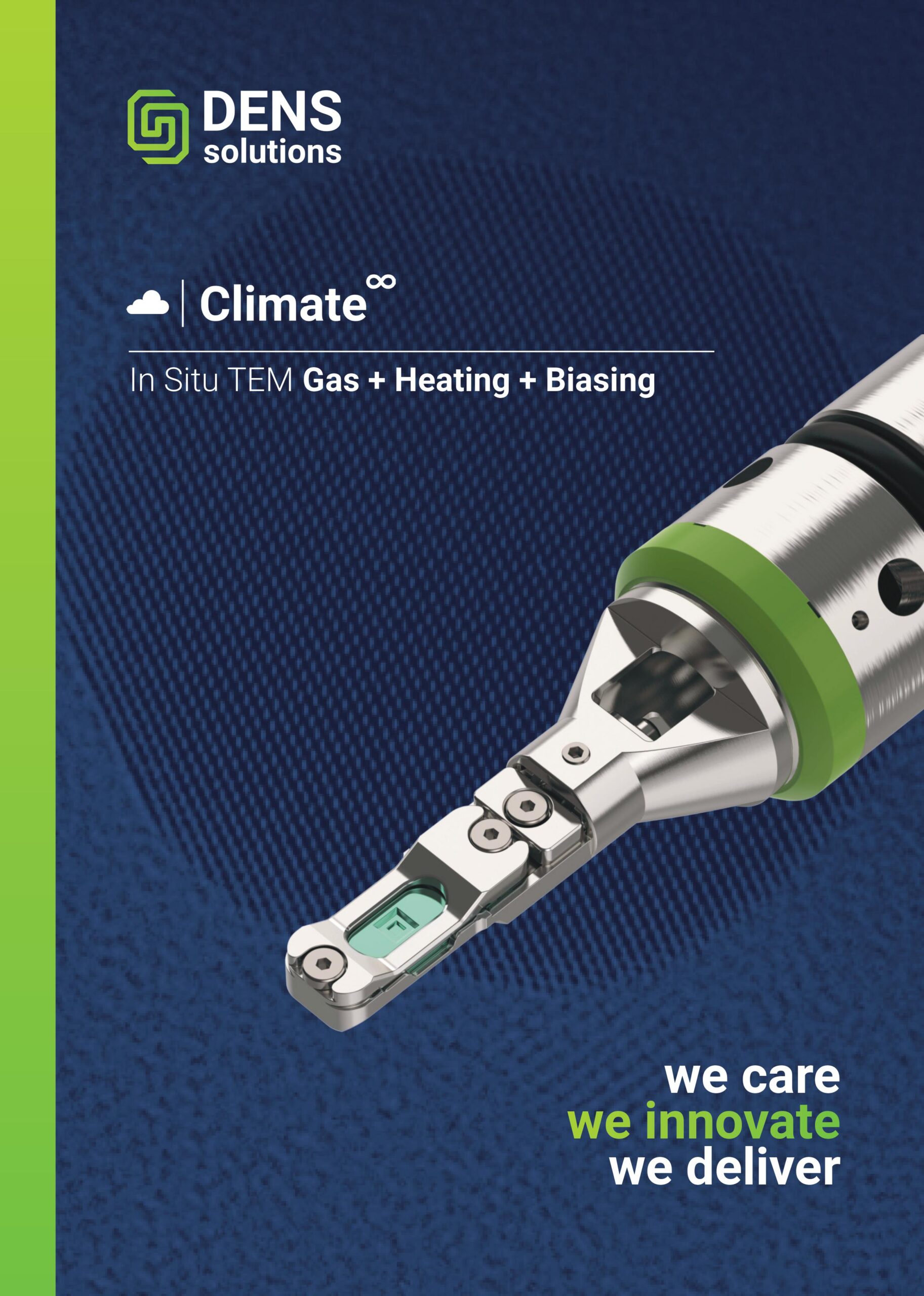
In Situ TEM Gas + Heating + Biasing
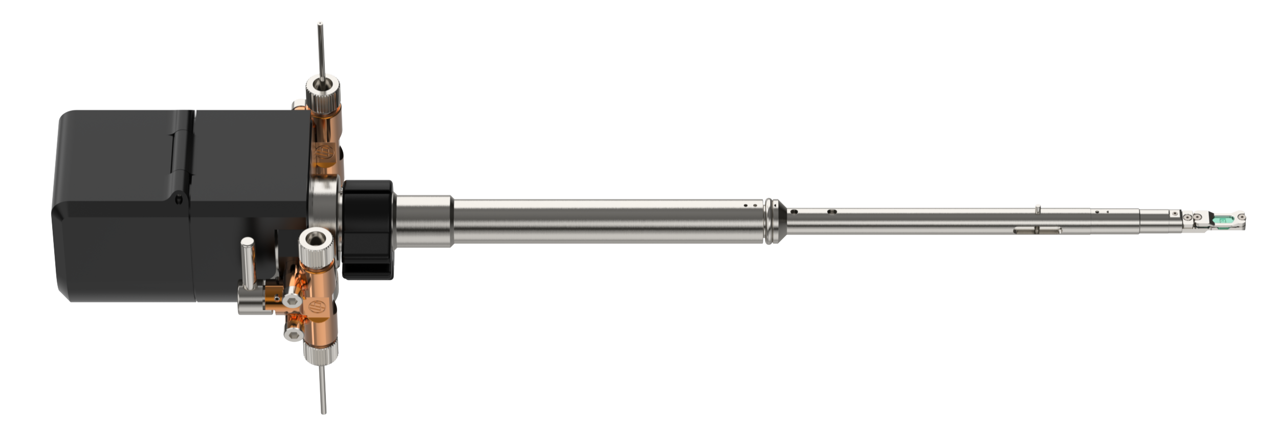
Expand your research capabilities with our new pioneering 8-contact environmental TEM holder, enabling simultaneous in situ electrical and thermal characterization of samples in controlled gas environments.
Application Fields

Nanomaterial growth

Catalysis

Fuel cells

Corrosion
Application Fields
Nanomaterial growth
Catalysis
Fuel cells
Corrosion
Climate Infinity Capabilities
Discover new potential for your in situ experiments.
1) Apply heating and biasing stimuli
The new Climate Infinity holder features eight electrical contacts that enable simultaneous application of electrical and thermal stimuli in a gas environment. The contacts can be used for various electrically driven MEMS-based sensors and actuators, making the Infinity platform essentially a research playground.
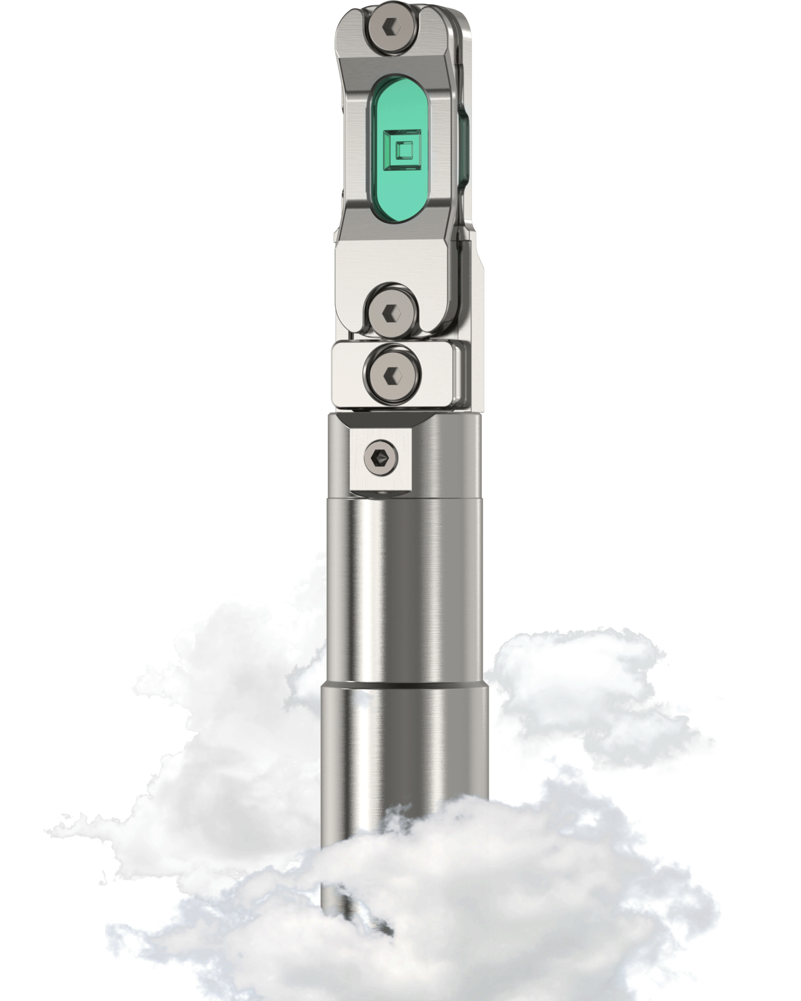
2) Easily switch between STEM and TEM mode
By flipping the tip 180 degrees, you can directly change the sample position to be either on the top or bottom without a need to disassemble the tip. This grants you the freedom to flawlessly switch between STEM or TEM mode, respectively, depending on your experimental needs, while maintaining the best resolution performance. Importantly, you can switch between both imaging modes within a matter of seconds.
3) Securely transfer your sample from one microscope to the other
The universal tip of the Infinity holder works as a cartridge that can be moved from one holder body to another, without disassembling the universal Nano-Reactor. This feature enables complementary cross-platform studies of the same sample in SEM, beamline setups or using TEM’s from JEOL or Thermo Fisher Scientific (TFS). These setups can either be located in the same lab, user facility or even in different universities/institutes, allowing for correlating experimental results in different platforms.
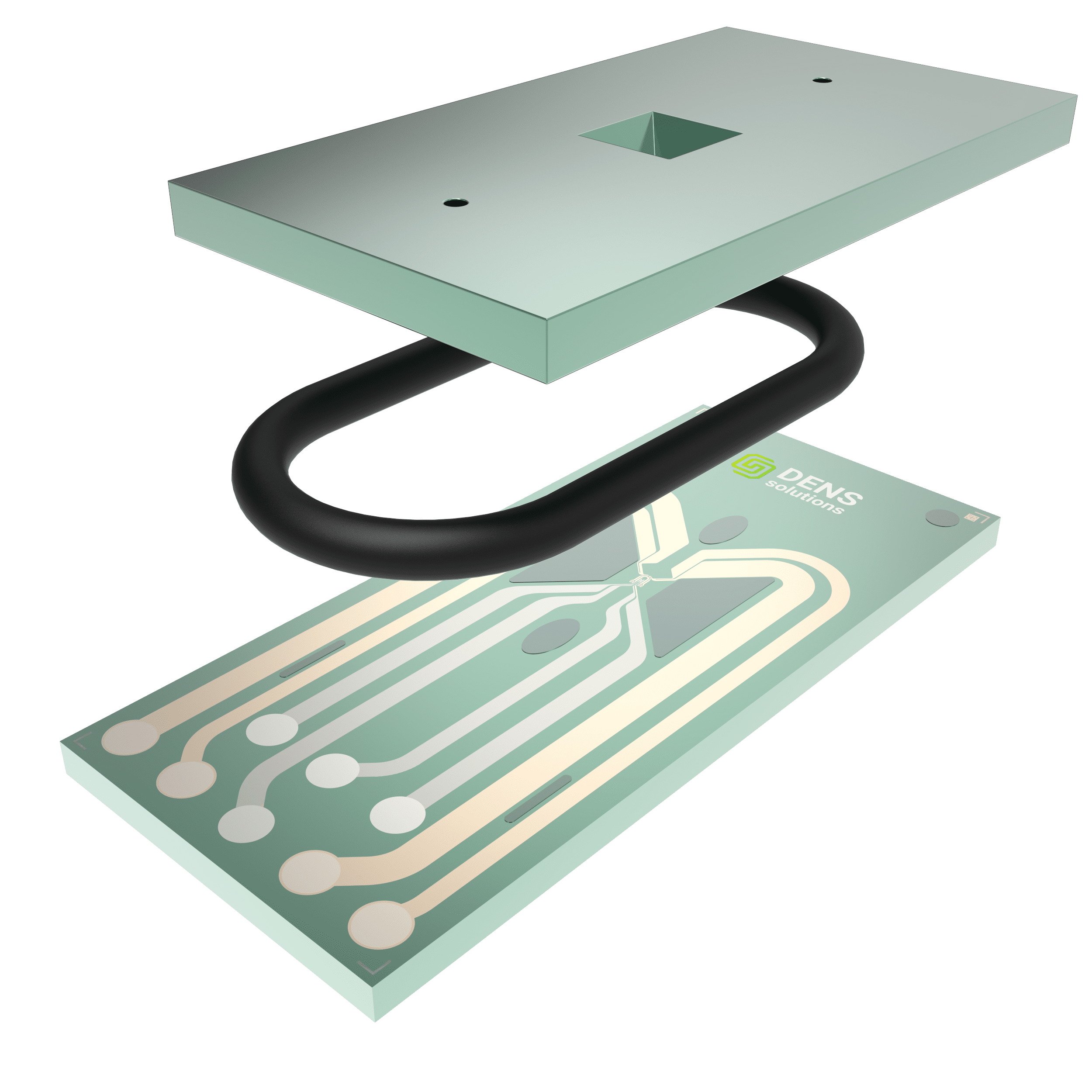
4) Perform gas and liquid studies with the same holder
The new environmental Infinity holder is your all-in-one solution for both gas and liquid experiments. Simply choose the appropriate function for the chips and connect the necessary gas or liquid supply system. Our extensive range of chip types includes gas-heating (GH), liquid-heating (LH), gas-heating-biasing (GHB), and liquid-heating-biasing (LHB), offering unparalleled versatility for your experimental needs. New MEMS chip designs can further expand the application space of the Infinity system.
Visualize the complete experimental workflow
From sample deposition to dynamic temperature and voltage control—explore it all.
News Article
Learn more about Climate Infinity in the article below.

Introducing Infinity: DENSsolutions’ new pioneering 8-contact environmental in situ solution
An interview with DENSsolutions’ Senior Mechanical Engineer about our latest innovation, Infinity – an environmental holder with combined heating and biasing capabilities in both gas and liquid environments.
Featured Application Notes
Explore Climate in typical application examples.

Structure evolution of iron oxides in reduction process

The reconstruction behavior of NiAu bimetallic nanoparticles under a hybrid water-hydrogen atmosphere

Correlative analysis of methane oxidation catalyzed by palladium
Frequently Asked Questions
Uncover the answers to your most frequently asked inquiries.
Can I safely use the Climate Infinity holder in my TEM?
Yes. The Climate Infinity holder dimensions are designed within the specifications for the applicable objective lens pole piece as provided by the TEM manufacturer (Thermo Fisher Scientific or JEOL). As long as the holder is also used within the Z- and T-axis range specified in the user manual, there should be no risk of the holder touching the pole piece. Before every insertion of the Climate Infinity holder into the TEM goniometer, it is tested for vacuum leaks with a turbomolecular pump. Only after this test is passed successfully, the user can continue to the next step of TEM insertion.
What is the preparation time for a typical experiment?
Preparing the Climate Infinity holder to run an experiment typically takes 20 minutes or less, depending on the user experience:
- 5-10 minutes to assemble the holder: placing the O-rings and the Nano-Reactor into the tip and closing off the lid
- 10 minutes to check the leak-tightness of the holder before TEM insertion
This time excludes sample preparation as this can vary from sample to sample.
What type of samples can be used inside the Climate Infinity Nano-Reactor?
The typical samples used with the Climate Infinity holder are catalyst nanoparticles which can be locally drop-casted onto the electron transparent windows of the functional Nano-Chip. 2D materials, nanowires and FIB lamellas can also be prepared onto the windows using a wet/dry transfer process, drop-casting and/or a focused ion beam (FIB) microscope, respectively; for every sample type, there is a dedicated sample preparation procedure.
How long does it take to replace the gas tubing?
The Climate holder has individually replaceable tubing and it takes about 5 minutes to replace the tubing. Fused Silica is the standard material of the tubing, but this can be changed for PEEK or another material if required by the user.
Can the sample position be changed from the top to the bottom window for optimum STEM or TEM imaging?
Yes. The Climate Infinity holder has a removable and symmetric tip. Once the holder is assembled, the user can choose the orientation of the sample, e.g. on the top or the bottom window by rotating the whole tip by 180 degrees along the holder axis. Notably, flipping the tip is a quick and easy process, taking less than a minute to complete.
In the standard configuration, the sample is located on the top window which is optimum for STEM imaging. When the tip is rotated, the sample position is optimum for TEM mode.
What gases can be used in the Climate Infinity system?
The list of permitted gases is determined based on whether that gas will interact with the materials used in the Nano-Reactor, Sample Holder and Gas Supply System. The materials in which the gas will be in contact with include silicon nitride, stainless steel, PEEKsil, titanium, fused silica, PEEK, etc. Typical gases that can be used with the Climate Infinity system are CxHy, O2, H2, N2, He, Ar, CO, CO2 and air. To know the exact gases that can be used, please refer to the chemical resistance sheet.
Any gases that can severely react with the above materials at room temperature (or at elevated temperatures for silicon nitride) should be avoided. If these gases are critical to your experiment, it is possible to dilute them to a safe level, however, this should be done in consultation with DENSsolutions. Alternative materials for some components are possible to extend the chemical compatibility range. Kindly reach out to DENSsolutions to discuss.
Is it possible to perform liquid experiments with the Climate Infinity holder?
Yes. The Climate Infinity holder is identical in terms of the design to the Stream Infinity holder and, as such, it can be used in combination with liquids. To enable in situ liquid heating and/or electrochemistry experiments in the TEM, Stream Nano-Cells, and a Liquid Supply System need to be used in combination with the Climate Infinity holder. To avoid cross-contamination between gas and liquid experiments, it is advized to have a dedicated tip and a set of tubings and O-rings for liquid research.
Is Climate Infinity compatible with EDS and EELS?
Yes, it is possible to use EDS and EELS techniques in combination with the Climate Infinity older. Very good EELS spectra can be produced even at pressures as high as 2 bar. The primary electron beam from the microscope will have minimal interaction with the Nano-Reactor windows or the small volume of gas inside. The newly introduced flippable tip and the Nano-Reactor allow the collection of higher-quality EDS spectra and maps.


Download the Climate Infinity Brochure
For more information on workflow, applications and specifications.
Request a quote
Request a quotation for any of our products.
Contact us
Get in touch with us for any questions you may have.