Scientists develop a powerful distributed electron microscopy technique to study complex reactions in solution

Scientists develop a powerful distributed electron microscopy technique to study complex reactions in solution

Using our Ocean system, scientists demonstrate the power of combining multiple electron microscopy methods, showing for the first time how the desilication mechanism of zeolite crystals proceeds in 3D on the single particle level.

Original article by Hanglong Wu, Teng Li, Sai P. Maddala, Zafeiris J. Khalil, Rick R. M. Joosten, Brahim Mezari, Emiel J. M. Hensen, Gijsbertus de With, Heiner Friedrich, Jeroen A. van Bokhoven and Joseph P. Patterson
Thomas article feature image
Liquid phase electron microscopy (LPEM) possesses the potential to revolutionize materials science by providing direct evidence of processes occurring in solution at the nanoscale. However, the use of high-energy electrons can be problematic as it can significantly change the solution chemistry and the liquid sample being imaged. Therefore, a primary challenge in LPEM is understanding the role the electron beam plays in the observed mechanism. As such, researchers find themselves stuck on the same question: “Which features of the native process are being captured?”

Dr. Hanglong Wu and his colleagues from the Eindhoven University of Technology, ETH Zurich and University of California, Irvine provide a robust answer to this pressing question by developing a novel approach for studying complex reactions in solution. This concept, which they term a “distributed electron microscopy (EM) method” combines information from multiple EM methods, including LPEM, cryogenic EM and cryo-electron tomography. To demonstrate this powerful method, Dr. Wu and his colleagues use our dedicated LPEM solution to study the desilication mechanism of zeolite crystals. They show for the first time with an exceptional level of confidence how the reaction proceeds in 3D on the single particle level. Moreover, they show how LPEM can be combined with cryo-EM to study a complete reaction which is essential to rule out beam-induced effects in LPEM experiments. 

The desilication study

Dr. Wu and his colleagues employ a distributed electron microscopy method to study the desilication process in zeolite crystals, showing how the reaction proceeds in 3D and what controls the desilication kinetics. This distributed approach enables them to explore and understand the native mechanism at hand, exploiting the power of each imaging modality – LPEM, cryogenic EM (cryo-EM) and cryo-electron tomography (cryo-ET). The researchers use Al-zoned ZSM-5 zeolites, which have an aluminum-rich rim and an aluminum-poor core, as a model system, to study the desilication process. The reason this is an ideal model system is that ZSM-5 crystals have a complex 3D morphology and are also considerably beam-sensitive.

The two videos below respectively show the automated sample loading process assisted by a liquid handling machine called SciTEM, and how the desilication process was initiated via the manual flowing of an NaOH solution into the cell.

Movie 1: Movie showing the SciTEM-assisted sample loading process, where a tiny droplet (~ 300 pL) containing zeolite crystals was deposited on the centre of the viewing window area.

Movie 2: Movie showing that the liquid cell is gradually filled with 0.6 M NaOH

Using LPTEM to observe the desilication process

Using LPTEM, Dr. Wu and his colleagues monitored the desilication process of individual parent zeolite crystals in multiple areas of a single cell. In the movie below, the desilication process of three pre-etched zeolite crystals can be observed over a 3-hour period. In contrast, for the crystals without the pre-etching treatment, the researchers find that the zeolites were only partially desilicated after 30 h in the liquid cell.

Movie 3: Movie showing the desilication process of three pre-etched zeolite crystals. On the left is the raw data movie and on the right a 30-frame-averaged data movie

The LPTEM data collected by the researchers provide evidence that desilication propagates along the c-axis beginning either at the Al-rich/Si-rich interface or in the crystal center. Moreover, it is observed that for the intergrowth structures, the process begins at the intergrown interface. Importantly, the LPEM experiments show that the confinement in the liquid cell slows down the desilication kinetics and that the electron beam does in fact influence the morphological evolution. This then raises the question that Dr. Wu and his colleagues sought out to answer: which features of the native desilication process are actually being captured?

LPTEM vs. LPSTEM

The LPSTEM results (Figure 1) observed by the researchers were significantly different from the LPEM observations. Dr. Wu and his colleagues believe that the differences mainly originate from contrast formation mechanisms and the localized electron distribution of each imaging mode. On one hand, LPTEM enables the quick control of the localized low electron flux homogeneously across the field of view. However, the appearance of diffraction contrast from the defects can be problematic for quantitative contrast interpretations. On the other hand, LPSTEM enables the better understanding of sample contrast evolution due to being less affected by diffraction effects. Simultaneously, however, the focused high flux electron probe might bring localized structural changes caused by radiolysis of the sample itself and water.

Figure 1 Hanglong article11

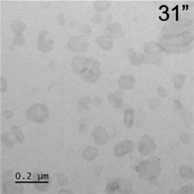
Figure 1: Desilication process of Al-zoned ZSM-5 crystals imaged by pulsed LP-STEM. Scale bars: 200 nm.

The LPSTEM results provide evidence that desilication proceeds by a sequential two-step process. Because the STEM probe scanning accelerates the etching process, this enabled the desilication process to be visualized with apparently “native” kinetics, thereby overcoming the confinement effects in the liquid cell. However, as beam effects were observed at all applied electron doses, the question remains: which features of the native desilication process are being captured?

Using cryo-EM and cryo-ET to observe the desilication process

Monitoring the desilication process using cryo-EM was the next step for Dr. Wu and his colleagues. Unlike LPEM, cryo-EM enabled the researchers to monitor the process in the absence of confinement and electron beam effects. In practice, cryo-TEM is generally performed prior to an in situ study, as it provides key information on what intermediate structures are present and, most importantly, how they evolve statistically over time. The figure below shows the cryo-EM results presented for crystals at different time points, where the stages of desilication are in agreement with the collective LPEM data and the general sample evolution observed by cryo-EM.

Figure 2 Hanglong article

Figure 2: Desilication process of ZSM-5 zeolites monitored by cryo-TEM (a) and cryo-STEM (b). Scale bars: 200 nm.

To verify the 3D interpretation of the desilication process, cryo-ET was performed on four crystals at an intermediate state of desilication. The movie below shows the cryo-ET reconstruction of a 12-hour desilicated zeolite crystal and Figure 3 shows the corresponding segmented surface rendering of the crystal.
Figure 3 Hanglong article

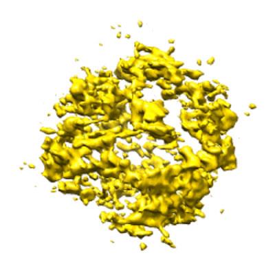
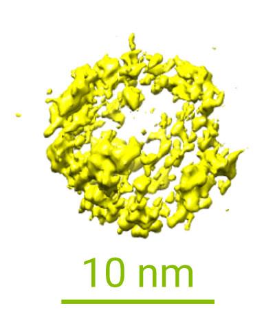
Figure 3: Segmented surface rendering of the 12 h desilicated zeolite crystal.

Movie 4: Movie showing the cryo-electron tomography 3D reconstruction of a 12 h desilicated zeolite crystal

Collectively, with the cryo-EM results, Dr. Wu and his colleagues were finally able to distinguish which information provided by LPEM observations represents the native desilication and which is an artifact. The cryo-EM data supported the hypothesis from both LPTEM and LPSTEM that desilication propagates along the c-axis. Moreover, it confirmed that it should occur in a two-step process, where both processes begin at the Al-rich/Si-rich interface and propagate toward the center of the crystal. This suggests that the LPTEM data either represents an artifact caused by the electron beam, confinement within the liquid cell, the sample preparation, or that the intermediates of this process are too transient to be captured by the cryo-EM data.

Novelty in findings

This study is a major step forward in understanding the role that the electron beam plays in LPEM experiments. Ultimately the collective results reveal that the desilication mechanism of zeolite crystals occurs via a two-step anisotropic etching process. This complex mechanism was only discovered due to the novel distributed approach that Dr. Wu and his colleagues employed. Particularly, the combination of LPEM and cryo-EM was essential to rule out the effects of the electron beam in the LPEM experiments.

Considering the strength of this distributed method, Dr. Wu and his colleagues anticipate that the combination of LPEM and cryo-EM will become a standard approach for understanding reaction mechanisms in aqueous solutions and could even be extended to non-aqueous solutions. Moreover this method will enable scientists to draw robust conclusions on the 3D reaction mechanisms of other important beam-sensitive material systems, such as biomaterials and proteins, whereby some grand challenges in materials science and life sciences could be potentially solved.

Hanglong Wu portrait
“DENSsolutions offers a simple but reliable solution for us to look into materials processes in liquid at the nanoscale. Currently, it is still difficult to observe the same phenomena in different liquid cells. That’s why people always joke that each LPEM experiment is “unique”. However, using the Ocean system, we have almost made every single “unique” LPEM experiment reproducible.”
Dr. Hanglong Wu
Postdoctoral Researcher |  Eindhoven University of Technology

Original article:

Discover our LPEM solutions:

Discover more publications made possible by our LPEM solutions:

Thomas article feature image

Scientists present novel approaches to map and control liquid thickness in LPEM experiments

Using our Ocean system, scientists present new approaches to overcome the limitations in LPEM experiments by quantitatively mapping and controlling liquid layer thickness.

Subscribe to our newsletter to stay up-to-date with the latest in situ microscopy news.

Scientists present novel approaches to map and control liquid thickness in LPEM experiments

Scientists present novel approaches to map and control liquid thickness in LPEM experiments

Using our Ocean system, scientists present new approaches to overcome the limitations in LPEM experiments by quantitatively mapping and controlling liquid layer thickness.

Original article by Hanglong Wu, Hao Su, Rick R. M. Joosten, Arthur D. A. Keizer, Laura S. van Hazendonk, Maarten J. M. Wirix, Joseph P. Patterson, Jozua Laven, Gijsbertus de With, Heiner Friedrich

Thomas article feature image

Liquid phase electron microscopy (LPEM) presents itself as a fundamental technique in the monitoring of nanoscale material processes in real-time. However, there are many challenges faced by the LPEM community with regard to quantifying and controlling liquid layer thickness to achieve laboratory-scale solution conditions and high-resolution imaging.

Using our dedicated LPEM solution, Ocean, Dr. Heiner Friedrich and his team at the Eindhoven University of Technology have paved the way for the better design of LPEM experiments and improved control of solution chemistry. Specifically, they present a simple low-dose method to quantitatively map the liquid layer thickness throughout the entire viewing area of any liquid cell with minimal beam effects even during repeated measurements. Moreover, they show how you can dynamically modulate liquid thickness by tuning the internal pressure in your liquid cell. Ultimately, this paper is a major step forward in the realization of LPEM experiment designs where bulk laboratory-scale solution conditions can be achieved yet at high resolutions. 

Mapping liquid layer thickness

Mapping the liquid layer thickness throughout the entire viewing area is crucial to avoid changes to the chemical environment but still provide the necessary information to 1) estimate which resolution can be reliably achieved, 2) model beam effects and 3) control the liquid thickness throughout the experiment.

Dr. Friedrich and his team use a simple low-dose method to map the liquid layer thickness throughout the entire viewing area. They did so by first acquiring two low-magnification, low-dose TEM images: one flat field image with no electron flux information, and another image with information on the number of electrons locally transmitting the viewing area. This information, combined with the silicon nitride (SiNₓ) membrane thickness, was then used to approximate the liquid layer thickness across the sample. The figure below shows in d) the intensity map of the viewing window area in a water-filled cell, and in e) the liquid layer thickness map calculated from the intensity map using the developed method. Shown in f) is the absolute liquid thickness map obtained from the same liquid cell in (d,e) using well-established STEM-EELS measurements.

Figure 1 - Schematic overview and mapping

Figure 1: a) to c) show the schematic overviews of the liquid cell. d) to f) show the resulting original intensity map, the calculated thickness map using the developed method and the absolute liquid thickness map obtained from the same liquid cell using STEM-EELS measurements, respectively.

The advantages of this method are that it can be adapted to any liquid and microscope which makes it a versatile tool for different experiments. This can be done by approximating the corresponding elastic mean free path (EMFP) from the chemical composition of the liquid and the acceleration voltage of the employed microscope.

Preparing the liquid cell

To prepare the liquid cell, the researchers employed a rather rare machine called the SciTEM (Scienion AG, a CELLINK company, Germany), which automates the liquid handling. The SciTEM is capable of patterning picoliter droplets of solutions onto the chip surface with a predefined array, and automatically loading the top chip to close the liquid cell. Ultimately, this means that accurate liquid volume control and reproducible liquid cell assembly can be achieved. The video below shows this process.

Movie 1: the automated preparation of the liquid cell

Controlling liquid thickness via internal pressure modulation

Because a pressure difference exists between the liquid and the microscope vacuum, the bending of the SiNₓ membrane windows typically occurs. This results in a spatially varying liquid layer thickness that makes it challenging to interpret LPEM results due to a locally varying achievable resolution and diffusion limitations. Therefore, to improve LPEM methodology, one needs to be able to accurately and dynamically control the liquid layer thickness, which has to be achieved by modulating the pressure inside the liquid cell.

Dr. Friedrich and his team show that with reproducible inward bulging of the window membranes, an ultra-thin liquid layer in the central window area for high-resolution imaging can indeed be realized. This is depicted very well in the figure below, showing the evolution of the meniscus in a liquid cell during evaporation. When evaporation occurs (2b), the flat gas-liquid interface gradually becomes curved, and the corresponding radius of curvature becomes smaller. At the same time, outward bulging is being reduced. Finally, as shown in 2d) and 2e), the inward bulging of the membrane is expected.

Figure 2 - Meniscus evolution with evaporation

Figure 2: Evolution of the meniscus in a liquid cell during evaporation

As shown in the in situ LPTEM video below, the liquid cell experienced outward bulging at the very beginning and within 3 minutes, nearly no bulging at all. Shortly after, you can see that an inward-bulged cell was obtained, entirely consistent with the model shown in Figure 2 above. Figure 3 demonstrates this, along with the corresponding intensity profile changes of the diagonal line across the window.

Movie 2: LPEM video showing outward to inward bulging in liquid cell

Figure 3 - Outward to inward bulging

Figure 3: Reversible transformation of a liquid cell containing water from outward to inward bulging via slow evaporation. Below are the intensity and thickness profiles of the bulging transition.

Rapid and dynamic control of liquid thickness

In addition, Dr. Friedrich and his team show that one can dynamically alter liquid thickness in a programmed fashion. They do this by independently controlling the inlet and outlet pressure on the fly via pressure pumps, and therefore the internal pressure inside the cell. Specifically, they show how pressure cycling gives rise to rapid dynamic control over liquid thickness, thus providing an additional adjustable parameter for experiment design. This dynamic control over the liquid layer thickness is depicted in the video below, where liquid thickness was continually mapped during the pressure cycling.

Movie 3: Rapid dynamic control of liquid layer thickness during external pressure cycles. The corresponding intensity and thickness maps are also shown.

Rapid dynamic control over liquid thickness is of key importance, in particular in bypass liquid cell systems, as it can help to overcome confinement problems such as diffusion limitations. In this way, the path can be paved towards achieving bulk solution conditions.

Novelty in findings

This paper contributes on two important fronts. Namely, it provides promising approaches to map and control liquid layer thickness in LPEM experiments with high accuracy and reliability. Using the above approaches, novel LPEM experimental designs with liquid thickness tailored to the requirement of the imaged process become imaginable. We are proud of the role that our LPEM solutions have played in making this research possible and strive to continue enabling groundbreaking research now and in the future.

Dr. Heiner Friedrich
“With this work on measuring and controlling liquid layer thickness using the Ocean system we hope to enable better science in the art of liquid phase electron microscopy.”
Dr. Heiner Friedrich
Assistant Professor |  Eindhoven University of Technology

Original article:

Discover our LPEM solutions:

Discover more publications made possible by our LPEM solutions:

Thomas article feature image

New measuring technique proves exceptional temperature accuracy of our Wildfire Nanochip

In collaboration with Utrecht University, we develop a novel technique to measure temperature at the nanoscale, showing the remarkable temperature accuracy and homogeneity of our Wildfire Nanochip

Do you want to receive great articles like this in your mailbox? Subscribe to our newsletter.

The first direct observation of pharmaceutical non-classical crystallization

The first direct observation of pharmaceutical non-classical crystallization

Using the Ocean system, scientists achieve supersaturation in LPEM experiments, revolutionizing pharmaceutical crystallization


Original article by Jennifer Cookman, Victoria Hamilton, Simon Hall and Ursel Bangert

LPEM video showing the pre-crystallization process of flufenamic acid

Whereas classical crystallization deals with layer-by-layer growth of crystals, non-classical crystallization (NCC) involves multiple different crystallization pathways towards the formation of final stable crystals. Although NCC has been widely documented in research, there is still much to be explored regarding the intermediate stages of crystallization and their direct observation. This is especially true for small organic molecules like flufenamic acid (FFA), an anti-inflammatory drug used for the treatment of rheumatic disorders.

Using the DENSsolutions Ocean LPEM system, Dr. Jennifer Cookman from the Bernal Institute in the University of Limerick and her colleagues were able to capture the intermediate pre-crystalline stages of this small organic molecule. This research marks the first ever direct observation of a pharmaceutical material undergoing NCC, highlighting the rising value and importance of in-situ TEM techniques in the pharmaceutical industry. 

The observed processes of NCC

Crystallization is a fundamental process that occurs in nature to produce some of the most common materials in daily life, such as the popular active pharmaceutical ingredient (API) ibuprofen or FFA. Properties such as solubility and bioavailability are linked to the crystal structure of the active compound. Considering APIs are commonly polymorphic, it is important to understand the intermediate stages of their crystallization. Specifically, if we can identify polymorphs with more desirable properties in the intermediate stages of crystallization, then this opens the door to harnessing and potentially directing their formation.

In this study, Dr. Cookman and her colleagues observed in situ the processes involved in the nanoscale crystallization of FFA. As illustrated in the figure below, this process involves four stages: aggregation, coalescence into a metastable entity, nucleus formation, and finally, crystallization.

A summary of the observed processes involved in the nanoscale crystallization of FFA

The researchers observed that FFA begins as a collection of small independent pre-nucleation clusters (PNCs). These PNCs are essentially stable particle clusters that form prior to the nucleation of a solid phase. They were able to follow three notable aggregates of PNCs that each followed the same transformational events. Particularly, after aggregation, these PNCs each independently coalesced, or merged, and formed a metastable phase. After this, the densification and development of a nucleus occurs, leading to the formation of FFA crystals. The processes of coalescence and densification will be further discussed and depicted below.

Coalescence

The aggregation of the PNCs were shown to have occurred prior to the researchers’ initial observations. Therefore the primary transformation observed for the three aggregates was actually that of coalescence. In the image below, you can see clearly that for each of the three selected aggregates, the individual clusters merge to form one cohesive entity after approximately 3 minutes.

A time-lapse of each of the three aggregates of PNCs undergoing coalescence

Densification towards crystallization

Following coalescence is the densification and development of a nucleus. This nucleus is formed by the successive sacrifice of surrounding material, leading to the formation of a new crystalline-like object, significantly more electron dense than before. Whereas coalescence took around 3 minutes, this densification occurred rapidly in under 10 seconds. The image and three videos below depict this rapid pre-crystallization process of FFA. 

A frame-by-frame summary of the three aggregates illustrating the pre-crystallization process of FFA

Aggregate 1

Aggregate 2

Aggregate 3

Novelty in findings

This research contributes academically in that the direct observations reported for the crystallization of FFA reveal insightful new information about the potential pathways towards crystallization. Moreover, it highlights the need to further investigate the nucleation and resulting crystallization of other small organic molecules via in situ techniques such as LPEM. LPEM presents itself as a required and complementary tool to not only comprehend but also probe chemistry at the nanoscale. This is true especially in regards to the crystallization of pharmaceutical ingredients, in which the development of the end product highly depends on controlling at the molecular building block level. 

The novelty of this research also lies in that it sheds light on the crystallization and nucleation of pharmaceutical products, providing the necessary information to further refine industrial-scale processes. If we can observe and understand the crystallization pathways that small organic molecular crystals like FFA take, we can better streamline production activities and develop effective manufacturing processes for generic drugs. It is precisely our goal at DENSsolutions to enable researchers like Dr. Jennifer Cookman to continue to bridge gaps in research using our solutions and uncover results that can impact this world, in the pharmaceutical industry and beyond.  

DENSsolutions Jennifer Cookman

“The DENSsolutions Ocean holder is a simple solution to native environment metrology that has the potential to revolutionize how we view pharmaceutical crystallization.”


“The DENSsolutions Ocean holder is a simple solution to native environment metrology that has the potential to revolutionize how we view pharmaceutical crystallization.”

Dr. Jennifer Cookman
Post Doctoral Researcher | University of Limerick

Original article:


Discover our latest LPEM solution, Stream:

Discover more publications made possible by Ocean:

Do you want to receive great articles like this in your mailbox? Subscribe to our newsletter.

First Visualisation of Crystal Growth from Organic Molecules

First Visualisation of Crystal Growth from Organic Molecules

Scientists characterise how flufenamic acid, a COX inhibitor, which is used in multiple industries, forms crystals from a liquid solution

Original article by Jennifer Cookman, Victoria Hamilton, Louise S. Price, Simon R. Hall and Ursel Bangert. Published in Nanoscale, issue 7, 2020.

The earliest stages of crystal growth are key to determining the final structure of a crystal, and scientists have visualised this process for the first time. Organic molecules were formed and grown in a liquid environment and characterised using the DENSsolutions Ocean In Situ system for Liquid Phase Electron Microscopy (LPEM).

Experimental Firsts

“Using LCEM (liquid cell electron microscopy) it has been possible for the first time to capture early-stage nucleation events of organic molecular crystals used as APIs (active pharmaceutical ingredients),” said Dr Jennifer Cookman from the Bernal Institute at the University of Limerick and lead researcher for this study.

“The importance of this method is that we can begin to understand how one crystal structure forms over another and, even more importantly, how these early-stage nucleation events manifest. We can also compare/contrast with classical nucleation theory and other crystal growth theories.”

The molecule studied, flufenamic acid, is a COX-inhibitor that acts as an anti-inflammatory. With increased study of this molecule, which is used in the pharmaceutical industry, researchers can potentially fine-tune its action as a medicinal drug and reduce its side-effects.

What’s more, the molecular crystalline state is widely used across many industries; including electronics and agrochemicals. This research represents the first steps to analysing molecular crystal growth of not just flufenamic acid, but other molecules with implications for improvements in other industries.

A 55-second video of flufenamic acid crystal growth at a scale of 0.5 micrometers. This video is remarkable as it shows the entire process of crystal nucleation, from a blank screen through nucleation to crystals. A good region to examine is the central point just above the 0.5 μm scale. A crystal forms here and grows without getting cluttered by other crystals.

Techniques and Methods

The Ocean LPEM system’s unique ability to perform transmission electron microscopy in a liquid ethanol environment was essential for this research. Dr Cookman adds that by “using the DENSsolutions Ocean holder we were able to introduce an undersaturated liquid solution of the API to be visualised in the TEM protected from the high vacuum environment of the TEM.” Then crystal growth was induced by illuminating the sample with an electron beam which provided the energy needed to prompt the nucleation process.

In situ microscopy far exceeds previous ex situ observations as the team could produce live footage of each stage of crystal growth. Additionally, the in situ technique enabled the visualisation of the nucleation of flufenamic acid molecules in a working environment, a.k.a. ethanol. Performing this analysis in a liquid environment as opposed to a vacuum helped to meaningfully ascertain where and how different physical arrangements of crystal structures occur.

“This work brings focus to the use of electron microscopy and in particular in situ TEM equipment for characterisation,” added Dr Cookman. “That can be of utmost importance to the pharmaceutical industry and also in interim characterisation in pharmaceutical crystal research.”

Micrographs showing crystals forming from flufenamic acid and growing into hexagonal crystals. A 0.2-micrometer scale is used for reference.

Wider Importance

It is at this earliest stage of growth that molecules can exhibit polymorphism; crystal structures that are composed of the same molecules but have different physical arrangements. Understanding how different crystal structures form from the same molecule type is desirable for research that needs nanoscale precision. For example, crystals are commonly used in medicines as a way to deliver active chemicals.

The antiretroviral drug, Ritonavir, which is used to treat HIV/AIDS, was pulled from circulation after it was found to contain a polymorphed version of the active drug. The polymorphed form was less biologically active and did not work as intended. Understanding these early steps in crystal growth is key to fine-tuning processes such as drug delivery.

Future Research

Advances in film technology and TEM allowed for direct observation of the nucleation process and this research represents the potential progress in the field of crystallisation. The results indicate that, with more research, scientists can discern the initial phases of crystal growth. This new technique opens up the field of TEM to visualising other crystallisation pathways, interrogate nucleation mechanisms, and explore new innovations.

The research was part of an EU Horizon 2020 FET-Open project named MagnaPharm which focuses on the magnetic control of polymorphism in pharmaceutical compounds. The team, which includes Dr Ursel Bangert and Dr Simon Hall, intend to continue to characterise flufenamic acid and different growth outcomes under different concentrations.

Learn more about our latest LPEM system ‘Stream’:

Discover more publications made possible by our Ocean system:

Read the original article:

Do you want to receive great articles like this in your mailbox? Subscribe to our newsletter.

Our partnership with the EPSRC/Jeol Centre for Liquid Phase Electron Microscopy at UCL, London

Our partnership with the EPSRC/Jeol Centre for Liquid Phase Electron Microscopy at UCL, London

DENSsolutions LPEM systems enable advances in Life Science

Dr. Lorena Ruiz-Perez (left) and Prof. Guiseppe Battaglia (right)

On the 12th of November, DENSsolutions in cooperation with UCL and Quantum Design UK will be holding a Stream workshop at the EPRSC/Jeol Centre for Liquid Phase Electron Microscopy (LPEM) facility at UCL, London. At the LPEM facility, opened in 2017, Dr. Lorena Ruiz-Perez uses the DENSsolutions Liquid In Situ solutions to characterise soft organic nanomaterials via TEM imaging. In this article, we take a look at the LPEM research that Ruiz-Perez is doing within the Molecular Bionics lab.

Molecular Bionics

The goal of the group is to mimic specific biological functions and/or introduce operations that do not exist in nature by engineering bionic units made of polymers. This goal is achieved by a multidisciplinary team of chemists, physicists, mathematicians, engineers and biologists.

The LTEM team at the Molecular Bionics group is formed by Prof. Guiseppe Battaglia, director of the facility, Dr. Lorena Ruiz-Perez, manager of the facility. Cesare de Pace and Gabriele Marchello are PhD students involved in the experimental development of LTEM and LTEM image analysis respectively.

Inside the group, Dr. Lorena Ruiz-Perez has been using the DENSsolutions Ocean system to work mainly on two different projects.

Polymer assemblies

For the first project, she has been using the system to investigate soft matter polymer assemblies. As we have shown in one of our earlier articles, these assemblies have the potential to be used for targeted drug delivery inside the human body. These kinds of assemblies have been well studied using Cryogenic electron microscopy (cryo-EM). One of the main advantages of employing LPEM is that it allows us to gain new insights into the dynamic behaviour of these assemblies within a liquid that were not possible using images of the vitrified, i.e. frozen sample. In liquid, you can observe for instance the fluctuation of the polymer assembly membranes and hence investigate significant mechanical properties of the soft materials.

Proteins dynamic behaviour

Their second project involves investigating the dynamic behaviour of proteins in liquid. These proteins move by the so-called ‘Brownian motion’. The group wants to understand the structure of the proteins inside their native environment. While the protein is moving in water, they can capture many different profiles in order to reconstruct a 3D image of the protein structure. There is a minimum frame amount needed for the reconstruction, so the time component becomes fundamental in these in-situ studies. The investigation aims to create a library of proteins, like the RCSB PDB, with information on dynamic processes which can complement the information already supplied by the well established cryo-EM technique. Their first results, studying ferritin proteins, were presented at Manchester 2019*.

Schematic representation showing the temporal evolution of the density map reconstruction process of ferritin. A five second long video was segmented into five one second long sub-videos The brownian particle analysis algorithm extracted about 1000 particle profiles from each sub-video, generating five different density maps. The quality and resolution of the refined density maps resulted in being inversely proportional to the sample exposure time to the electron beam.

Proteins play a pivotal role in our physiological conditions and associated diseases. A deeper understanding of the kinetics governing the mechanistic behaviour of proteins in liquid media can lead to big improvements in drug design and ultimately in general healthcare.

*This manuscript is currently being updated with long molecular dynamics simulations of ferritin in solution.

The new Stream system

Now the group is advancing to the DENSsolutions Stream system, allowing them to do new kinds of experiments. The big advantage of the Stream system is that it can control the bulging of the viewing windows and therefore the liquid thickness. Controlling the bulging is essential for creating reproducible results. In previous LPEM in situ systems, the window bulging could differ between experiments, thus preventing experiment reproducibility.

Now with the Stream system, the bulging can be adjusted precisely for each new experiment, guaranteeing the same level of bulging and, therefore, consistent results. Controlling the liquid thickness is also important to achieve high contrast in organic and biological materials. The liquid thickness can be reduced up to the equilibrium where you have the highest possible resolution combined with a thick enough layer to have a realistic sample environment. 

Learn more about our Stream system:

Discover publications in which our Ocean system was used:

Do you want to receive interesting articles like this in your mailbox? Subscribe to our newsletter.

Membranes made from Nano-droplets have potential in Medical Research

Membranes made from Nano-droplets have potential in Medical Research

Membranes formed in-lab from nano-droplets could have future use in medicines

For the first time, researchers from the Laboratory of Materials and Interface Chemistry, Eindhoven University of Technology (TUE), with a significant contribution of assistant professor Joe Patterson, have made a comprehensive video of liquid membrane formation using a transmission electron microscope (TEM). They used soap-like nanodroplets submerged in water to create the membrane. Their results are published in Nature, Chemistry and have been highlighted in the Nature, Chemistry News & Views article ‘The molecular Lego movie’.

LPEM Movie of the in-situ self-assembly experiment. Stabilized and cropped. Ianiro, A. et al. Nat. Chem. (2019)

This experiment has continuously recorded the whole process of how the membrane is formed under a microscope. Before this, scientists had to freeze the final membrane and get a snapshot of one or several moments of the membrane forming. This advance is achieved due to a well controlled liquid environment and can be now set in the microscope thanks to the DENSsolutions Ocean system.

Screenshots from the video of the membrane forming on the silicon chip. These were taken using a transmission electron microscope. You can watch the full video here. Ianiro, A. et al. Nat. Chem. (2019)
Membranes are of great interest in research as their selective barriers have potential uses in many fields: drug delivery, water treatment and chemical processes all rely on membrane technology. They are of particular interest in pharmaceutical research as they are the ideal shape to transport a drug through the body and release it only when the membrane finds a specific type of cell, for example, a cancer cell.

The Experiment

The researchers from the Materials and Interface Chemistry group led by Prof. Nico Sommerdijk formed a membrane from soap-like molecules called amphiphilic molecules, which simply means that they interact with both fats and water. Amphiphilic molecules are good building blocks for membranes as they can be lined up with the water-interacting side facing one way and the lipid-interacting parts facing the other way to form larger structures.

The DENSsolutions Ocean In Situ TEM liquid system was essential in this research. The core of the system consists of a dual chip Nano-Cell that sandwiches two chips together to form a microfluidic compartment.

First, the chambers within the tip surrounding the Nano-Cell were flooded with an amphiphilic solvent in order for it to fill the compartment. Then, the solvent was expelled with air, leaving the compartment saturated. Finally, the tip was flooded with water which gradually diffused into the compartment. It was during this stage that the water particles encouraged the solvent particles to organise themselves into a membrane structure.

Step 1. Polymer solvent

Step 2. Air

Step 3. Water

The membrane itself formed in stages. First, the solvent molecules arranged themselves into nanodroplets with a hydrophobic core and a protective hydrophilic shell. The DENSsolutions Nano-Cell created a hotspot of these nanodroplets and they gradually arranged themselves into a hollow membrane.
Diagram of the amphiphilic membrane forming in water. Arash Nikoubashman and Friederike Schmid.

Future Research

Watching how the nanoparticles form and arrange themselves with an electron microscope is a huge step in learning how to manipulate these membranes. The techniques covered in this research will be of interest to scientists working in food science, synthesis chemistry and separation science.

Hanglong Wu, who made a significant contribution to this paper during his PhD period, commented in an interview with DENSsolutions, that the technique “has been extensively used in studying the dynamics and structures of hard materials (for example, metallic nanoparticles) in the aqueous solution in the last decade, but it has been barely employed into soft matter field, mainly due to the inherent high beam sensitivity and low contrast.

“In this Nat. Chem. paper, we actually demonstrate we can probe the soft matter formation with such high contrast. People for sure will start to use the technique in the soft matter field.” – Hanglong Wu

The next stage will be fine-tuning how to manipulate the size and shape of the membrane. This research from Eindhoven is an important step in an exciting field.

If you are interested in the equipment we provided for this research, then contact us to see how we can streamline your experiments.

Membranes formed in-lab from nano-droplets could have future use in medicines

For the first time, researchers from the Laboratory of Materials and Interface Chemistry, Eindhoven University of Technology (TUE), with a significant contribution of assistant professor Joe Patterson, have made a comprehensive video of liquid membrane formation using a transmission electron microscope (TEM). They used soap-like nanodroplets submerged in water to create the membrane. Their results are published in Nature, Chemistry and have been highlighted in the Nature, Chemistry News & Views article ‘The molecular Lego movie’.

LPEM Movie of the in-situ self-assembly experiment. Stabilized and cropped. Ianiro, A. et al. Nat. Chem. (2019)

This experiment has continuously recorded the whole process of how the membrane is formed under a microscope. Before this, scientists had to freeze the final membrane and get a snapshot of one or several moments of the membrane forming. This advance is achieved due to a well controlled liquid environment and can be now set in the microscope thanks to the DENSsolutions Ocean system.

Screenshots from the video of the membrane forming on the silicon chip. These were taken using a transmission electron microscope. You can watch the full video here. Ianiro, A. et al. Nat. Chem. (2019)
Membranes are of great interest in research as their selective barriers have potential uses in many fields: drug delivery, water treatment and chemical processes all rely on membrane technology. They are of particular interest in pharmaceutical research as they are the ideal shape to transport a drug through the body and release it only when the membrane finds a specific type of cell, for example, a cancer cell.

The Experiment

The researchers from the Materials and Interface Chemistry group led by Prof. Nico Sommerdijk formed a membrane from soap-like molecules called amphiphilic molecules, which simply means that they interact with both fats and water. Amphiphilic molecules are good building blocks for membranes as they can be lined up with the water-interacting side facing one way and the lipid-interacting parts facing the other way to form larger structures.

The DENSsolutions Ocean In Situ TEM liquid system was essential in this research. The core of the system consists of a dual chip Nano-Cell that sandwiches two chips together to form a microfluidic compartment.

First, the chambers within the tip surrounding the Nano-Cell were flooded with an amphiphilic solvent in order for it to fill the compartment. The solvent was then expelled with air, leaving the compartment saturated. Then, the solvent was expelled with air, leaving the compartment saturated. Finally, the tip was flooded with water which gradually diffused into the compartment. It was during this stage that the water particles encouraged the solvent particles to organise themselves into a membrane structure.

Step 1. Polymer solvent

Step 2. Air

Step 3. Water

The membrane itself formed in stages. First, the solvent molecules arranged themselves into nanodroplets with a hydrophobic core and a protective hydrophilic shell. The DENSsolutions Nano-Cell created a hotspot of these nanodroplets and they gradually arranged themselves into a hollow membrane.
Diagram of the amphiphilic membrane forming in water. Arash Nikoubashman and Friederike Schmid.

Future Research

Watching how the nanoparticles form and arrange themselves with an electron microscope is a huge step in learning how to manipulate these membranes. The techniques covered in this research will be of interest to scientists working in food science, synthesis chemistry and separation science.

Hanglong Wu, who made a significant contribution to this paper during his PhD period, commented in an interview with DENSsolutions, that the technique “has been extensively used in studying the dynamics and structures of hard materials (for example, metallic nanoparticles) in the aqueous solution in the last decade, but it has been barely employed into soft matter field, mainly due to the inherent high beam sensitivity and low contrast.

“In this Nat. Chem. paper, we actually demonstrate we can probe the soft matter formation with such high contrast. People for sure will start to use the technique in the soft matter field.” – Hanglong Wu

The next stage will be fine-tuning how to manipulate the size and shape of the membrane. This research from Eindhoven is an important step in an exciting field.

If you are interested in the equipment we provided for this research, then contact us to see how we can streamline your experiments.