Improved insight into catalytic reduction of NOx for industrial processes

Improved insight into catalytic reduction of NOx for industrial processes

In Situ TEM supports the design process of a new nanorod catalyst

Original article by Zhaoxia Ma, Liping Sheng, Xinwei Wang, Wentao Yuan, Shiyuan Chen, Wei Xue, Gaorong Han, Ze Zhang, Hangsheng Yang, Yunhao Lu, and Yong Wang. Published in Advanced Materials, volume 31, issue 42.

Artist impression showing growth of carbon nanotubes via an iron-catalyzed process. © 2019 DENSsolutions All Rights Reserved

There is a big opportunity for the design and development of sustainable catalysts for low-temperature NOx removal in the steel, cement and glass industries. Researchers Dr. Yong Wang et al. from Zhejiang University made a recent breakthrough using critical information obtained by In Situ TEM to design a MnOx/CeO2 nanorod (NR) catalyst with outstanding resistance to SO2 deactivation. Former studies proposed methods which succeeded in temporarily diminishing the influence of SO2 but lost their effectiveness over time. In this study, a dynamic equilibrium was achieved between sulfates formation and decomposition over the CeO2 nanorod surface, resulting in an unchanged NOx reaction rate for 1000 hours.

In Situ TEM study

Up till now, researchers have not been able to see exactly what happens to the CeO2 catalyst particle when exposed to SO2 because SO2 is so corrosive that it would damage the environmental transmission electron microscope (ETEM). Now, thanks to the DENSsolutions Climate in situ TEM Gas and Heating system, scientists can for the first time observe and record this degradation process at the atomic scale. Dr. Wang’s team found out that non-active amorphous cerium sulfates were formed from the reaction between SO2 and CeO2. The cerium sulfates formed a deposit which gradually coated the crystalline surface of the nanorods that was catalytically active.

Video 1. In situ TEM observation of the formation and evolution of cerium sulfate over Ce02 nanorods during treatment in 1000 ppm NO, 1000 ppm SO2, and 10 vol% 02 balanced with Ar at 523K. The two white arrows point to amorphous bumps at the end of Ce02 nanorods.

Video 2. In situ TEM observation of dynamic evolution of cerium sulfates during treatment in 1000 ppm NO, 1000 ppm NH3, and 10 vol% 02 balanced with Ar at 523K. The white dashed circles indicate the amorphous cerium sulfate bumps, which decomposed after the introduction of NH3.

In the first part of the In Situ TEM experiment, the researchers introduced diluted SO2 to study the deactivation behaviour of CeO2. Many obvious bumps were formed on the surface of the CeO2 nanorods (NR); this dynamic formation process can be seen in video 1. After this step, the researchers used their Climate Gas Supply System to switch off the SO2 gas flow to the TEM and switched on the diluted NH3 gas flow. The researchers could then observe the amorphous cerium sulfate bumps to become smaller and finally almost disappear at 523 K. The decomposition of the cerium sulfate bumps can be seen in video 2. This change back to polycrystalline CeO2 can be seen in detail in video 3.

Video 3. In situ TEM observation of dynamic evolution of a single cerium sulfate bump during treatment in 1000 ppm NO, 1000 ppm NH3, and 10 vol% 02 balanced with Ar at 523K. The white arrow points to amorphous cerium sulfates, which retransformed into crystalline Ce02 after the introduction of NH3.

Image 1. DENSsolutions Gas Supply System

The Gas Supply System (image 1) of the Climate G+ gas & heating system can continuously mix (dilute) gas flows from up to 3 sources. The mixing ratios for these 3 gas flows, typically 1 reducing, 1 oxidizing and 1 inert (carrier) gas, can be changed real-time between 0% and 100% according to the requirements of the in situ TEM experiment. This makes it the ideal tool for new discoveries in gas-solid interactions.

“Thanks to the state-of-the-art gas cell system from DENSsolutions, we can simply move the industrial reactions into the TEM and observe what really happens for the catalysts during reactions with atomic resolution at atmospheric pressure. This is the first time we attempted to introduce industrial gases like NH3 and SO2 to the gas cell system. To our surprise, this system was pretty robust and worked perfectly when studying the catalytic reactions involved in SO2 poisoning.”

Dr. Yong Wang – Zhejiang University

Learn more about our Climate system and Nano-Reactor:

Discover more publications made possible by our Climate system:

Read the original article:

Do you want to receive great articles like this in your mailbox? Subscribe to our newsletter.

Visualizing the dynamic behaviours during carbon nanotube growth in extensive detail

Visualizing the dynamic behaviours during carbon nanotube growth in extensive detail

In situ TEM allows for the direct observation of catalytic processes at relevant pressure and temperature conditions

Original article by Xing Huang, Ramzi Farra, Robert Schlögl and Marc-Georg Willinger

Artist impression showing growth of carbon nanotubes via an iron-catalyzed process. © 2019 DENSsolutions All Rights Reserved

Carbon nanotubes (CNTs) hold many promises, for example in energy storage, high-performance catalysis, photovoltaics, and biomedical devices. Although industrial-scale production of CNTs has been realised, the controllability over the diameter, length, and chirality of CNTs is still unsatisfactory. This is largely due to the lack of atomic information on growth dynamics of CNTs and molecular-level understanding of growth mechanisms. Recently, Huang et al. from FHI Berlin and ETH Zürich have performed an In Situ TEM study on CNT growth and disclosed the growth and termination dynamics of CNTs in atomic detail under relevant conditions. 

The stability of the DENSsolutions Nano-Reactor and the possibility to introduce stimuli, like gas and heating, allowed for the live observation at the atomic-scale:

In Situ TEM video made using the DENSsolutions Climate system, showing Fe-catalyzed multiwalled carbon nanotube growth. Temperature: 800 °C, pressure: 178.65 mbar, diluted H2 + C2H4.

Using In Situ TEM gas and heating, the researchers were able to reveal the influence of pressure and temperature on the growth of CNTs. Previous studies were contradictory about the active state of the catalyst. Now with real-time observations of CNT growth at relevant conditions, researchers were able to reveal not only the active phase of the catalyst but also the rich structural dynamics of the catalyst during the course of CNT growth.

In this study, the Nano-Reactor, the core of the DENSsolutions Climate In Situ TEM system, was used as a carrier for the Fe2O3 sample (precursor material for CNT growth), which was then heated in a diluted hydrogen gas flow as a pre-treatment. The In Situ experiment was started at 150 °C and was followed by a step wise increase up to 800 °C in a gas mixture of H2, C2H4 and He.

To accelerate catalyst research, the DENSsolutions Climate system can be delivered with a dedicated Gas Supply system that enables instant switching between gases and precise control over the gas mixture ratio.

Between 450 °C and 650 °C, the reduction of Fe2O3 to Fe3O4 was accompanied by a collapse of larger particles into smaller ones.

Did you know?

Our Impulse control software comes with a drag & drop profile builder that allows you to design & automate your experiment. It features a wide choice of parameters which enable you to create profiles that suit any sample and application.

WATCH THE VIDEO >

“Thanks to the development of the MEMS-based gas flow Nano-Reactor, we are allowed to perform In Situ experiments inside the chamber of the TEM at relevant conditions. Using the Climate system from DENSsolutions, we have recently carried out a detailed In Situ study on the growth behaviors of CNTs at realistic conditions. On the basis of the real-time observations, we are able to reveal the active structure of the working catalyst and its dynamic re-shaping during the course of CNT growth. Extended observations further reveal three different scenarios for the growth termination of CNTs at the atomic-scale. The presented work provides important insights into understanding the growth and termination mechanisms of CNTs and may serve as an experimental basis for rational design and controlled synthesis of CNTs.”

First and corresponding author – Dr. Xing Huang, ETH Zürich

Learn more about our Climate system and Nano-Reactor:

Discover more publications made possible by our Climate system:

Read the original article:

Do you want to receive great articles like this in your mailbox? Subscribe to our newsletter.

Converting CO2 into a valuable energy carrier using a model In2O3 catalyst

Converting CO2 into a valuable energy carrier using a model In2O3 catalyst

New discoveries made possible by In Situ TEM gas and heating

Original article by Athanasia Tsoukalou, Paula M. Abdala, Dragos Stoian, Xing Huang, Marc-Georg Willinger, Alexey Fedorov and Christoph R. Müller. Published in the Journal of the American Chemical Society on 19 July 2019.

Artist impression of methanol synthesis via CO2 hydrogenation using In2O3 catalyst (copyright of the American Chemical Society)

The direct hydrogenation of CO2 to methanol shows promise to be an important technique to reduce the amount of greenhouse gases in the atmosphere and thereby mitigate the negative effects of climate change while producing an important energy carrier. In his contribution to this article, Dr. Xing Huang has used In Situ TEM techniques to assess the limits of In2O3 catalytic performance in CO2 hydrogenation.

In Situ TEM Climate Nano-Reactor study

This catalyst research article by ETH Zürich provides a good demonstration on how in situ TEM experiments can add value to the study of reaction mechanisms. First, the structural changes in the catalyst material were studied with traditional TEM techniques before and after the CO2 reduction. By using the Climate in situ TEM system, the researchers were able to see the dynamics of the reaction, even at much lower pressures (0.8 vs. 20 Bar) than in the original operando experiment.

In Situ TEM video made using the DENSsolutions Climate system, at 300 °C, showing the co-existence of crystalline and amorphous phases as well as the transformation into film structures of the In2O3 catalyst.

Amorphization of the catalyst material inside the Nano-Reactor takes places in a few minutes, compared to hours in the capillary reactor. Re-activation of the catalyst is made easy by the Climate Gas Supply System since the hydrogen plus carbon-dioxide gas flow can be replaced by an oxygen flow at any moment.

“Direct observation using in situ TEM clearly reveals that the structure of In2O3 nanoparticles is highly dynamic under reaction conditions and irradiation of electron beam. The In2O3 is observed to transform into a dynamic structure in which both crystalline and amorphous phases coexist and continuously inter-convert.

This observation is in line with the operando XAS-XRD study revealing formation of the amorphous In0/In2O3 phase with time on stream. To sum up, combination of in situ TEM with other in situ/operando techniques enables to build a direct relationship between the structure and the catalytic performance of the In2O3 catalyst in CO2 hydrogenation to methanol.”

Co-author – Dr. Xing Huang, ETH Zürich

Learn more about our Climate system and Nano-Reactor:

Discover more publications made possible by our Climate system:

Real‐Time Imaging of Nanoscale Redox Reactions over Bimetallic Nanoparticles

Real‐Time Imaging of Nanoscale Redox Reactions over Bimetallic Nanoparticles

Shu Fen Tan, See Wee Chee, Zhaslan Baraissov, Hongmei Jin, Teck Leong Tan, Utkur Mirsaidov
Published in Advanced Functional Materials on 16 July 2019

Publication

Video 1: In situ TEM movie of a Pt–Ni rhombic dodecahedron NP undergoing oxidation reaction in 20% O2 / 80% N2 gaseous environment at 400 °C inside a gas cell.
Video 2: In situ TEM movie of a Pt–Ni rhombic dodecahedron NP undergoing reduction reaction in 5% H2 / 95% N2 gaseous environment at 400 °C inside a gas cell.

This recent article from National University of Singapore about the catalyst activity of bimetallic nanoparticles clearly demonstrates the versatility of the Climate G+ gas & heating system that was used for the in situ TEM experiments.

Figure S4. In situ TEM images showing the evolution of Pt–Ni NPs (A) before and (B) after the oxidation (20% O2 / 80% N2) reaction followed by (C) the reduction (5% H2 / 95% N2) reaction at 400 °C inside a gas cell. Here, t = 0 s marks the start of 20% O2 / 80% N2 flow. At t = 133.1 s, the gas mixture was switched to 5% H2 / 95% N2.

Fast switching between oxidizing and reducing gas conditions allows direct observation of the morphological changes in the catalyst material. The video’s above also demonstrate the UHR image stability at in situ conditions.

Combining the images and video’s from this experiment with SAED, EDS and Mass Spectroscopy results gives valuable information about the areas where the catalyst is most active.

Gas Analyzer supporting ex situ Catalyst experiments

Gas Analyzer supporting ex situ Catalyst experiments

Technical Research Engineer Marien Bremmer MSc with the gas analyzer (blue) in the background
Our solutions not only allow for highly controllable in situ experiments, they also allow for ex situ experiments that might save you valuable in situ time. With this ex situ experiment, we were able to prove the performance of the catalyst before moving in to the TEM.

The experiment

We used palladium nanoparticles for our catalyst These particles were dropcasted inside a Climate MEMS based Nano-Reactor. For the gas supply we used the Climate G+ system which allows for up to 3 gases to be mixed. We loaded the system with oxygen and methane as reactive gases and measured carbon monoxide and carbon dioxide as reaction products.

Figure 1. Sample temperature (top) and gas partial pressure (middle & bottom) measured as a function of time.

Catalyst performance

First we used the gas analyzer combined with our accurate temperature control to measure the catalyst performance. The supply of reactants was kept at a constant level (figure 1 – middle graph) while we used our Impulse software to automatically ramp up the temperature of the Nano-Reactor from 300 to 700 °C in 60 seconds (figure 1 – top graph). As a result we measured the level of reactant gases dropping and the level of reaction products rising (figure 1 – bottom graph). We see the levels stabilizing when the temperature is constant.


High activity phase shifting

Figure 2. Gas mixture composition into the Nano-Reactor (top), partial pressures of gases flowing out of the Nano-Reactor (middle) and dissipated power by the Nano-Reactor heater (bottom) as a function of time.
During the next experiment, we kept the palladium sample at a constant temperature while increasing the concentration of methane (CH4) from 5% to 10% (figure 2 – top graph). At around  t = 300 seconds you can clearly see fluctuations in the level of reaction products (figure 2 – middle graph). Here we observe the catalyst shifting in and out of a high activity phase that is reached at elevated temperatures. When passing a certain temperature range, this high activity phase can be demonstrated by oscillations in the partial pressure of the gas reaction products. Also oscillations in the power dissipated by the heater (figure 2 – bottom graph) indicates a change of activity at the sample.
At t = 500 seconds we use our Impulse software to drop the level of methane in steps of 0,5%. Measuring the COlevel with our gas analyzer we can clearly see the influence of the first drop in concentration. The COproduction rate starts to more unstable. By dropping the concentration with another 0,5%, the frequency of the fluctuations increases and, after the third drop of concentration, the catalyst starts to shift back to its normal activity phase, stabilizing the COproduction after the fourth drop.
 

High time resolution

Figure 3. Detailed results for partial pressure (top) and power dissipation (bottom) measurements.

We zoomed in at areas A and B and plotted the results from the gas analyzer as well as those from the power dissipated by our 4-point probe temperature control system (see figure 3). This allows us to correlate the two measurements. We see that the reaction gases are in counter phase of each other and that their extremes are in line with the tops of the measured power. This shows not only a very high stability in temperature control but also a very high time resolution.

Conclusions

Thanks to our high accuracy gas analyzer and heating control and measurement, you are able to do ex situ experiments that can give you valuable data. This data can lead to new discoveries or can be used to prepare your in situ experiment better.

Marien Bremmer who conducted the experiment commented:
“Using the Climate G+ in combination with the Gas Analyzer allows you to characterize your catalyst sample ex situ, finding the best gas and temperature conditions for your reaction, and with this data to go to the TEM to finalize your research with real in situ images and spectroscopy.”

Download the
Gas Analyzer Application Note

Technical Research Engineer Marien Bremmer MSc with the gas analyzer (blue) in the background
Our solutions not only allow for highly controllable in situ experiments, they also allow for ex situ experiments that might save you valuable in situ time. With this ex situ experiment, we were able to prove the performance of the catalyst before moving in to the TEM.

The experiment

We used palladium nanoparticles for our catalyst These particles were dropcasted inside a Climate MEMS based Nano-Reactor. For the gas supply we used the Climate G+ system which allows for up to 3 gases to be mixed. We loaded the system with oxygen and methane as reactive gases and measured carbon monoxide and carbon dioxide as reaction products.

Figure 1. Sample temperature (top) and gas partial pressure (middle & bottom) measured as a function of time.

Catalyst performance

First we used the gas analyzer combined with our accurate temperature control to measure the catalyst performance. The supply of reactants was kept at a constant level (figure 1 – middle graph) while we used our Impulse software to automatically ramp up the temperature of the Nano-Reactor from 300 to 700 °C in 60 seconds (figure 1 – top graph). As a result we measured the level of reactant gases dropping and the level of reaction products rising (figure 1 – bottom graph). We see the levels stabilizing when the temperature is constant.
 

High activity phase shifting

Figure 2. Gas mixture composition into the Nano-Reactor (top), partial pressures of gases flowing out of the Nano-Reactor (middle) and dissipated power by the Nano-Reactor heater (bottom) as a function of time.
During the next experiment, we kept the palladium sample at a constant temperature while increasing the concentration of methane (CH4) from 5% to 10% (figure 2 – top graph). At around  t = 300 seconds you can clearly see fluctuations in the level of reaction products (figure 2 – middle graph). Here we observe the catalyst shifting in and out of a high activity phase that is reached at elevated temperatures. When passing a certain temperature range, this high activity phase can be demonstrated by oscillations in the partial pressure of the gas reaction products. Also oscillations in the power dissipated by the heater (figure 2 – bottom graph) indicates a change of activity at the sample.
At t = 500 seconds we use our Impulse software to drop the level of methane in steps of 0,5%. Measuring the COlevel with our gas analyzer we can clearly see the influence of the first drop in concentration. The COproduction rate starts to more unstable. By dropping the concentration with another 0,5%, the frequency of the fluctuations increases and, after the third drop of concentration, the catalyst starts to shift back to its normal activity phase, stabilizing the COproduction after the fourth drop.
 

High time resolution

Figure 3. Detailed results for partial pressure (top) and power dissipation (bottom) measurements.

We zoomed in at areas A and B and plotted the results from the gas analyzer as well as those from the power dissipated by our 4-point probe temperature control system (see figure 3). This allows us to correlate the two measurements. We see that the reaction gases are in counter phase of each other and that their extremes are in line with the tops of the measured power. This shows not only a very high stability in temperature control but also a very high time resolution.

Conclusions

Thanks to our high accuracy gas analyzer and heating control and measurement, you are able to do ex situ experiments that can give you valuable data. This data can lead to new discoveries or can be used to prepare your in situ experiment better.

Marien Bremmer who conducted the experiment commented:
“Using the Climate G+ in combination with the Gas Analyzer allows you to characterize your catalyst sample ex situ, finding the best gas and temperature conditions for your reaction, and with this data to go to the TEM to finalize your research with real in situ images and spectroscopy.”

Download the
Gas Analyzer Application Note

UConn Opening a New Center for In Situ & Operando TEM in Collaboration With DENSsolutions

UConn Opening a New Center for In Situ & Operando TEM in Collaboration With DENSsolutions

UConn Tech Park (Magda Biernat)

At DENSsolutions, we believe that together we can achieve more. So, we are proud to announce our partnership with the University of Connecticut (UConn).

A new center commemorating this exciting collaboration will be opened. The UConn DENSsolutions Center for IN-siTu/Operando Electron Microscopy (InToEM) will be the home of scientists and engineers with complementary expertise working at the frontier of understanding materials dynamics. The InToEM center is situated in UConn Tech Park, the University of Connecticut’s premier center for cutting-edge research, industry collaboration, and innovation.

Our contribution

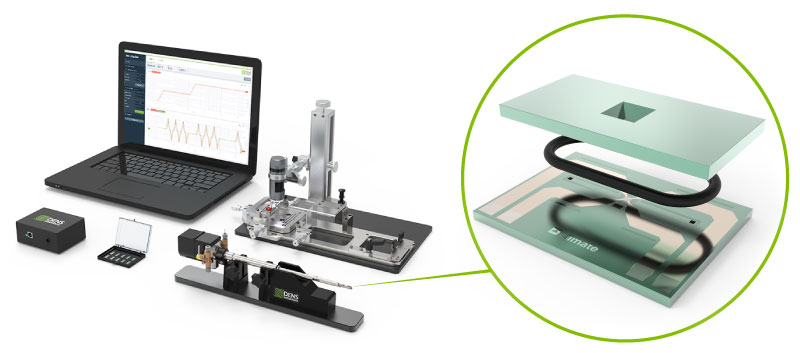
The DENSsolutions Climate MEMS-based Nano-Reactor TEM system will be at the heart of this research center. The system has a unique capacity to probe high-temperature gas-solid reactions with high spatial resolution under ambient pressure, in gaseous environment controlled by sophisticated dynamic gas mixing. Dynamic changes in local site-specific structural information of nanomaterials can be monitored in real-time under realistic reaction conditions.

Climate In Situ Gas & heating system with featured MEMS-based Nano-Reactor (gas supply not on the picture)
Climate In Situ Gas & heating system (gas supply not on the picture)
MEMS-based Nano-Reactor

New Opportunities

As the demands of research need more complex solutions, we want to move towards Operando environmental electron microscopy. Our solutions will allow concurrent mass-spectrometry, calorimetry and chemical analysis during reactions.
These new capabilities will provide unprecedented insight into the correlation between materials dynamics and temporal performance at the fundamental atomic-scale, and will open up a world of research opportunities in heterogeneous catalysis, fuel cells, corrosion, and materials growth and transformation.

Dr. Zhu with the Climate system (UConn Photo)
Yuanyuan Zhu, the Director of the InToEM, Assistant Professor in the Department of Materials Science and Engineering, Institute of Materials Science, UConn commented:
“Being able to study the behavior of materials in their native environment has been microscopist’s dream since the birth of TEM. I’m very excited about the InToEM center, which will provide an optimal scientific “sandbox” to explore microscopy as it should be.”
Ben Bormans, CEO of DENSsolutions, is very pleased to have UConn and the InToEM center led by Dr. Zhu, as a customer:
“DENSsolutions’ vision is that in situ and operando TEM can contribute to solving societal challenges like climate change and green/clean technologies.
These new techniques connect microscopy more meaningfully with chemistry, materials research and nanotechnology. Therefore, here at DENSsolutions, we all are very, very excited about being a partner in the InToEM center.
Here, a lot of good things come together: the Materials Science and Engineering Department and Institute of Materials Science of UConn with world-class performance in Materials research, the fantastic facilities of the Business Innovation Center, and the focus and passion of the scientists of INToEM.”

Download the Climate Brochure

For more information on features and specifications.

<!--[if lte IE 8]><!-- [et_pb_line_break_holder] --><script charset="utf-8" type="text/javascript" src="//js.hsforms.net/forms/v2-legacy.js"></script><!-- [et_pb_line_break_holder] --><![endif]--><!-- [et_pb_line_break_holder] --><script charset="utf-8" type="text/javascript" src="//js.hsforms.net/forms/v2.js"></script><!-- [et_pb_line_break_holder] --><script><!-- [et_pb_line_break_holder] --> hbspt.forms.create({<!-- [et_pb_line_break_holder] --> portalId: "469089",<!-- [et_pb_line_break_holder] --> formId: "0d52a62f-f229-49fb-a2d3-9b8c66a5a526", submitButtonClass: 'et_pb_button'<!-- [et_pb_line_break_holder] -->});<!-- [et_pb_line_break_holder] --></script>
UConn Tech Park (Magda Biernat)

At DENSsolutions, we believe that together we can achieve more. So, we are proud to announce our partnership with the University of Connecticut (UConn).

A new center commemorating this exciting collaboration will be opened. The UConn DENSsolutions Center for IN-siTu/Operando Electron Microscopy (InToEM) will be the home of scientists and engineers with complementary expertise working at the frontier of understanding materials dynamics. The InToEM center is situated in UConn Tech Park, the University of Connecticut’s premier center for cutting-edge research, industry collaboration, and innovation.

Our contribution

The DENSsolutions Climate MEMS-based Nano-Reactor TEM system will be at the heart of this research center. The system has a unique capacity to probe high-temperature gas-solid reactions with high spatial resolution under ambient pressure, in gaseous environment controlled by sophisticated dynamic gas mixing. Dynamic changes in local site-specific structural information of nanomaterials can be monitored in real-time under realistic reaction conditions.

Climate In Situ Gas & heating system with featured MEMS-based Nano-Reactor (gas supply not on the picture)
Climate In Situ Gas & heating system (gas supply not on the picture)
MEMS-based Nano-Reactor

New Opportunities

As the demands of research need more complex solutions, we want to move towards Operando environmental electron microscopy. Our solutions will allow concurrent mass-spectrometry, calorimetry and chemical analysis during reactions.
These new capabilities will provide unprecedented insight into the correlation between materials dynamics and temporal performance at the fundamental atomic-scale, and will open up a world of research opportunities in heterogeneous catalysis, fuel cells, corrosion, and materials growth and transformation.

Dr. Zhu with the Climate system (UConn Photo)
Yuanyuan Zhu, the Director of the InToEM, Assistant Professor in the Department of Materials Science and Engineering, Institute of Materials Science, UConn commented:
“Being able to study the behavior of materials in their native environment has been microscopist’s dream since the birth of TEM. I’m very excited about the InToEM center, which will provide an optimal scientific “sandbox” to explore microscopy as it should be.”
Ben Bormans, CEO of DENSsolutions, is very pleased to have UConn and the InToEM center led by Dr. Zhu, as a customer:
“DENSsolutions’ Vision is that in situ and operando TEM can contribute to solving societal challenges like climate change and green/clean technologies.
These new techniques connect microscopy more meaningfully with chemistry, materials research and nanotechnology. Therefore, here at DENSsolutions, we all are very, very excited about being a partner in the InToEM center.
Here, a lot of good things come together: the Materials Science and Engineering Department and Institute of Materials Science of UConn with world-class performance in Materials research, the fantastic facilities of the Business Innovation Center, and the focus and passion of the scientists of INToEM.”

Download the Climate Brochure

For more information on features and specifications.

<!--[if lte IE 8]><!-- [et_pb_line_break_holder] --><script charset="utf-8" type="text/javascript" src="//js.hsforms.net/forms/v2-legacy.js"></script><!-- [et_pb_line_break_holder] --><![endif]--><!-- [et_pb_line_break_holder] --><script charset="utf-8" type="text/javascript" src="//js.hsforms.net/forms/v2.js"></script><!-- [et_pb_line_break_holder] --><script><!-- [et_pb_line_break_holder] --> hbspt.forms.create({<!-- [et_pb_line_break_holder] --> portalId: "469089",<!-- [et_pb_line_break_holder] --> formId: "0d52a62f-f229-49fb-a2d3-9b8c66a5a526", submitButtonClass: 'et_pb_button'<!-- [et_pb_line_break_holder] -->});<!-- [et_pb_line_break_holder] --></script>