Liquid flow control: Unlock untapped research capabilities within in situ LPEM

Liquid flow control: Unlock untapped research capabilities within in situ LPEM

Via the unique on-chip microfluidic channel of the DENSsolutions Stream system, researchers were able to create a highly controlled chemical environment for visualizing the nanoscale metallic electrodeposition of copper crystals.

Original article by Cheng et al.

Liquid phase transmission electron microscopy (LPTEM) enables the observation of time-resolved dynamics in liquid state at high spatial resolution. The technique has gained exponential popularity over the last decade, and has contributed greatly to a wide range of fields, including materials science, chemistry and life science. With LPEM, researchers can explore the dynamical evolution of key materials and uncover fundamental insights into nucleation and growth. Only in recent years have researchers been able to control the chemical environment within an in situ LPEM experiment, owing to the award-winning innovation that is the DENSsolutions Stream system. In a recent publication, researchers including Dr. Ningyan Cheng from Anhui University utilized the Stream system to visualize the metallic electrodeposition of copper crystals in a highly controlled chemical environment. This was made possible due to the unique on-chip flow channel of Stream, which enables numerous advantages such as the ability to flush away beam-induced species, explore flow-dependent liquid dynamics and easily change electrolyte composition.

On-chip microfluidic channel

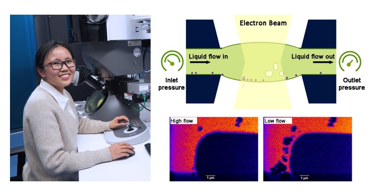
The core of the DENSsolutions Stream system is our patented Nano-Cell, which consists of a top and bottom chip, together forming a sealed compartment that enables users to safely perform liquid experiments inside the TEM. The bottom chip contains spacers, an integrated liquid inlet, flow channel and an outlet. Via pressure-based pumps, a liquid sample can be driven from the inlet through the field of view and then through the outlet. This process is demonstrated in the video below. Importantly, users can independently control the pressure at the inlet and outlet of the Nano-Cell, and therefore the absolute pressure in the microfluidic channel. This then enables full control over the liquid flow rate within the cell.

Movie 1: Animation depicting the microfluidic channel of the Stream Nano-Cell

Efficient liquid flow

Before observing any liquid phenomena in the TEM, Dr. Cheng and her fellow collaborators first had to ensure that the flow was efficient and well-controlled. To do this, the researchers first assembled a dry Nano-Cell. The flow was then initiated by turning on the pressure-based pump, while keeping all imaging parameters constant. After 30 seconds, the imaging contrast changed abruptly, implying that the liquid had definitely flowed into the Nano-Cell. This process is shown in the video below. The time taken to completely fill the Nano-Cell ranges anywhere from tens of seconds to just 3 minutes when a flow rate of 8 μl/min is applied.

Movie 2: In situ TEM movie showing the liquid flow into the Nano-Cell in just 30 seconds

Removal of beam-induced species

A key benefit of controlling the liquid flow within an LPEM experiment is the ability to remove beam-induced particles. The researchers first generated particles by increasing the electron flux on purpose through changing the spot size from 5 to 1. The process of removing the beam-induced species in this experiment is detailed in the video below, with the direction of the flow going from top to bottom. As soon as the flow was cut off at 6.4s, the particles started to form and grow on the membrane. The flow was then switched on again at 11.7 seconds, which is when the particles that were stuck to the membrane started to peel off and move from the top to the bottom area in the field of view. It took just 2 minutes to fully flush away the particles, which is a reproducible process. The direction of the particles’ movement is the same as the direction of the flow (top to bottom), confirming the effectiveness and power of the liquid flow control. 

Movie 3: Removal of beam-induced species via liquid flow control

Capturing flow-dependent liquid dynamics

The next step for the researchers was to explore the effect of the flow rate on the electrochemical copper crystallization and dissolution processes in real time. They first observed the effect of using a higher flow rate of 1.4 μl/min on the Cu deposition and dissolution processes, which showed to be reversible. The protocol included the initial electrode cleaning, deposition (−0.9 V, 10 s), dissolution (+0.4 V, 15 s) and repeating the process for 4 cycles. As demonstrated in the video below, the researchers found that uniform copper deposition can be obtained at a higher liquid flow rate (~1.4 μl/min), whereas at a lower liquid flow rate (0.1 μl/min), the growth of copper dendrites was observed. 

Movie 4: Copper electrodeposition at a flow rate of 1.4 μl/min (left) and 0.1 μl/min (right)

Changing electrolyte composition

Besides exploring the effects of altering the flow rate, a major point of interest in this study was observing the effect of adding foreign ions, such as phosphates, on the electrodeposition. Such additives can affect the electrochemically deposited crystals by, for example, changing the nuclei structures. The researchers first studied the electrodeposition of copper from a pure CuSO₄ aqueous solution. In this case, no obvious dendritic morphology was observed and instead only granules were formed (see below Figure 1, Left).

After the experiment, the electrolyte in the sample source was replaced by a mixture of CuSO and KHPO solution. The liquid was kept flowing with a flow rate of 3 μl/min for 15 min, which enabled the researchers to directly study the electrolyte effect on the depositions in the same liquid cell by excluding all the uncertainties during different cell assembly. Contrastingly in this case, copper dendrites were observed to grow and the addition of HPO− ions in the electrolyte led to the formation of Cu-phosphate complexes (see Figure 1, Right). These results further confirm the importance of being able to modulate the electrolyte composition, and demonstrate the effectiveness of the environment control that Stream enables.

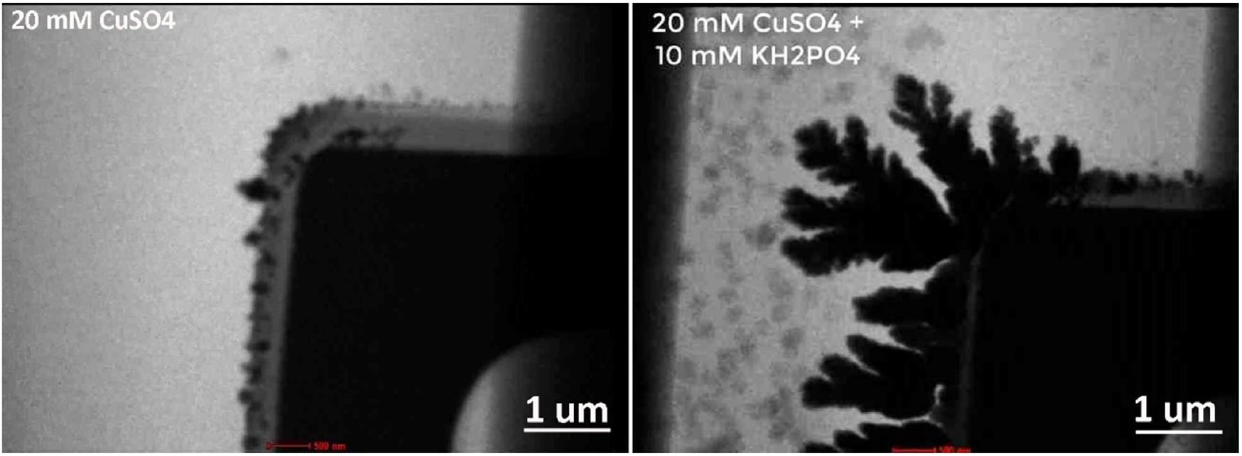
Figure 1: The effect of phosphate addition on Cu electrodeposition

Exploiting electrode design to alter the chemical environment

When studying Cu electrodeposition in the previous experiment, the researchers saw that dendrite formation can be further promoted by the in situ addition of foreign ions, such as phosphates. In order to confirm the generality of this technique, they also took a look at Zn electrodeposition in an aqueous solution of ZnSO. The figure below shows the total growth of the zinc layer at b) a lower potential of −0.9 V (versus Pt) in the first 10 seconds, and c) a higher potential of −1.1 V (versus Pt) in the next 10 seconds. In d) the total growth of the Zn depositions in the first 20 seconds is shown. The researchers observed in the first 10 seconds (−0.9 V) that the deposition on the inner edge is rougher compared to the outer edge. In the following growth at −1.1 V, dendritic depositions are nucleated and grown on the previous outer edge, while no further growth can be observed in the inner edge. This experiment demonstrates that the special electrode design of Stream enables the exploration of rich liquid dynamics within different chemical environments. 

Figure 2: Zinc electrodeposition in b) the first 10 seconds with a potential of −0.9 V and c) in the next 10 seconds with a potential of −1.1 V. d) shows the total Zn growth in the 20 seconds.

Conclusion

Through this study, it is shown that Stream’s distinctive ability to enable liquid flow control opens the doors for researchers to truly alter the chemical environment within the liquid cell. By controlling the liquid flow, a user can flush away beam-induced species, explore flow-dependent liquid dynamics and easily change electrolyte composition. Moreover, the unique design of the electrodes in the Stream system allows researchers to explore complex liquid dynamics within different chemical environments within the same liquid cell. Importantly, the direct observations made by Cheng et al. not only provide new insights into understanding the nucleation and growth, but also give guidelines for the design and synthesis of desired nanostructures for specific applications, such as high performance electrocatalysis for energy conversion and electrodes for secondary batteries. 

Hanglong Wu portrait

Image of Dr. Ningyan Cheng from Max-Planck-Institut für Eisenforschung GmbH

“The DENSsolutions Stream System not only provides a useful means to study a wide range of dynamics in solution, but also enables systematic studies of the effect of the chemical environment on the corresponding reactions through precise control of the flow rate, liquid composition and other significant parameters.” 

Prof. Dr. Ningyan Cheng   Associate Professor  |  Anhui University

Original article:

Discover our Stream solution:

Discover more publications made possible by Stream:

Thomas article feature image

Climate helps uncover phase coexistence and structural dynamics of redox metal catalysts

Using our Climate system, scientists are able to interrelate the atomic-scale structural dynamics of redox metal catalysts to their activity.

Subscribe to our newsletter to stay up-to-date with the latest in situ microscopy news.

Scientists develop a powerful distributed electron microscopy technique to study complex reactions in solution

Scientists develop a powerful distributed electron microscopy technique to study complex reactions in solution

Using our Ocean system, scientists demonstrate the power of combining multiple electron microscopy methods, showing for the first time how the desilication mechanism of zeolite crystals proceeds in 3D on the single particle level.

Original article by Hanglong Wu, Teng Li, Sai P. Maddala, Zafeiris J. Khalil, Rick R. M. Joosten, Brahim Mezari, Emiel J. M. Hensen, Gijsbertus de With, Heiner Friedrich, Jeroen A. van Bokhoven and Joseph P. Patterson
Thomas article feature image
Liquid phase electron microscopy (LPEM) possesses the potential to revolutionize materials science by providing direct evidence of processes occurring in solution at the nanoscale. However, the use of high-energy electrons can be problematic as it can significantly change the solution chemistry and the liquid sample being imaged. Therefore, a primary challenge in LPEM is understanding the role the electron beam plays in the observed mechanism. As such, researchers find themselves stuck on the same question: “Which features of the native process are being captured?”

Dr. Hanglong Wu and his colleagues from the Eindhoven University of Technology, ETH Zurich and University of California, Irvine provide a robust answer to this pressing question by developing a novel approach for studying complex reactions in solution. This concept, which they term a “distributed electron microscopy (EM) method” combines information from multiple EM methods, including LPEM, cryogenic EM and cryo-electron tomography. To demonstrate this powerful method, Dr. Wu and his colleagues use our dedicated LPEM solution to study the desilication mechanism of zeolite crystals. They show for the first time with an exceptional level of confidence how the reaction proceeds in 3D on the single particle level. Moreover, they show how LPEM can be combined with cryo-EM to study a complete reaction which is essential to rule out beam-induced effects in LPEM experiments. 

The desilication study

Dr. Wu and his colleagues employ a distributed electron microscopy method to study the desilication process in zeolite crystals, showing how the reaction proceeds in 3D and what controls the desilication kinetics. This distributed approach enables them to explore and understand the native mechanism at hand, exploiting the power of each imaging modality – LPEM, cryogenic EM (cryo-EM) and cryo-electron tomography (cryo-ET). The researchers use Al-zoned ZSM-5 zeolites, which have an aluminum-rich rim and an aluminum-poor core, as a model system, to study the desilication process. The reason this is an ideal model system is that ZSM-5 crystals have a complex 3D morphology and are also considerably beam-sensitive.

The two videos below respectively show the automated sample loading process assisted by a liquid handling machine called SciTEM, and how the desilication process was initiated via the manual flowing of an NaOH solution into the cell.

Movie 1: Movie showing the SciTEM-assisted sample loading process, where a tiny droplet (~ 300 pL) containing zeolite crystals was deposited on the centre of the viewing window area.

Movie 2: Movie showing that the liquid cell is gradually filled with 0.6 M NaOH

Using LPTEM to observe the desilication process

Using LPTEM, Dr. Wu and his colleagues monitored the desilication process of individual parent zeolite crystals in multiple areas of a single cell. In the movie below, the desilication process of three pre-etched zeolite crystals can be observed over a 3-hour period. In contrast, for the crystals without the pre-etching treatment, the researchers find that the zeolites were only partially desilicated after 30 h in the liquid cell.

Movie 3: Movie showing the desilication process of three pre-etched zeolite crystals. On the left is the raw data movie and on the right a 30-frame-averaged data movie

The LPTEM data collected by the researchers provide evidence that desilication propagates along the c-axis beginning either at the Al-rich/Si-rich interface or in the crystal center. Moreover, it is observed that for the intergrowth structures, the process begins at the intergrown interface. Importantly, the LPEM experiments show that the confinement in the liquid cell slows down the desilication kinetics and that the electron beam does in fact influence the morphological evolution. This then raises the question that Dr. Wu and his colleagues sought out to answer: which features of the native desilication process are actually being captured?

LPTEM vs. LPSTEM

The LPSTEM results (Figure 1) observed by the researchers were significantly different from the LPEM observations. Dr. Wu and his colleagues believe that the differences mainly originate from contrast formation mechanisms and the localized electron distribution of each imaging mode. On one hand, LPTEM enables the quick control of the localized low electron flux homogeneously across the field of view. However, the appearance of diffraction contrast from the defects can be problematic for quantitative contrast interpretations. On the other hand, LPSTEM enables the better understanding of sample contrast evolution due to being less affected by diffraction effects. Simultaneously, however, the focused high flux electron probe might bring localized structural changes caused by radiolysis of the sample itself and water.

Figure 1 Hanglong article11

Figure 1: Desilication process of Al-zoned ZSM-5 crystals imaged by pulsed LP-STEM. Scale bars: 200 nm.

The LPSTEM results provide evidence that desilication proceeds by a sequential two-step process. Because the STEM probe scanning accelerates the etching process, this enabled the desilication process to be visualized with apparently “native” kinetics, thereby overcoming the confinement effects in the liquid cell. However, as beam effects were observed at all applied electron doses, the question remains: which features of the native desilication process are being captured?

Using cryo-EM and cryo-ET to observe the desilication process

Monitoring the desilication process using cryo-EM was the next step for Dr. Wu and his colleagues. Unlike LPEM, cryo-EM enabled the researchers to monitor the process in the absence of confinement and electron beam effects. In practice, cryo-TEM is generally performed prior to an in situ study, as it provides key information on what intermediate structures are present and, most importantly, how they evolve statistically over time. The figure below shows the cryo-EM results presented for crystals at different time points, where the stages of desilication are in agreement with the collective LPEM data and the general sample evolution observed by cryo-EM.

Figure 2 Hanglong article

Figure 2: Desilication process of ZSM-5 zeolites monitored by cryo-TEM (a) and cryo-STEM (b). Scale bars: 200 nm.

To verify the 3D interpretation of the desilication process, cryo-ET was performed on four crystals at an intermediate state of desilication. The movie below shows the cryo-ET reconstruction of a 12-hour desilicated zeolite crystal and Figure 3 shows the corresponding segmented surface rendering of the crystal.
Figure 3 Hanglong article

Figure 3: Segmented surface rendering of the 12 h desilicated zeolite crystal.

Movie 4: Movie showing the cryo-electron tomography 3D reconstruction of a 12 h desilicated zeolite crystal

Collectively, with the cryo-EM results, Dr. Wu and his colleagues were finally able to distinguish which information provided by LPEM observations represents the native desilication and which is an artifact. The cryo-EM data supported the hypothesis from both LPTEM and LPSTEM that desilication propagates along the c-axis. Moreover, it confirmed that it should occur in a two-step process, where both processes begin at the Al-rich/Si-rich interface and propagate toward the center of the crystal. This suggests that the LPTEM data either represents an artifact caused by the electron beam, confinement within the liquid cell, the sample preparation, or that the intermediates of this process are too transient to be captured by the cryo-EM data.

Novelty in findings

This study is a major step forward in understanding the role that the electron beam plays in LPEM experiments. Ultimately the collective results reveal that the desilication mechanism of zeolite crystals occurs via a two-step anisotropic etching process. This complex mechanism was only discovered due to the novel distributed approach that Dr. Wu and his colleagues employed. Particularly, the combination of LPEM and cryo-EM was essential to rule out the effects of the electron beam in the LPEM experiments.

Considering the strength of this distributed method, Dr. Wu and his colleagues anticipate that the combination of LPEM and cryo-EM will become a standard approach for understanding reaction mechanisms in aqueous solutions and could even be extended to non-aqueous solutions. Moreover this method will enable scientists to draw robust conclusions on the 3D reaction mechanisms of other important beam-sensitive material systems, such as biomaterials and proteins, whereby some grand challenges in materials science and life sciences could be potentially solved.

Hanglong Wu portrait
“DENSsolutions offers a simple but reliable solution for us to look into materials processes in liquid at the nanoscale. Currently, it is still difficult to observe the same phenomena in different liquid cells. That’s why people always joke that each LPEM experiment is “unique”. However, using the Ocean system, we have almost made every single “unique” LPEM experiment reproducible.”
Dr. Hanglong Wu
Postdoctoral Researcher |  Eindhoven University of Technology

Original article:

Discover our LPEM solutions:

Discover more publications made possible by our LPEM solutions:

Thomas article feature image

Scientists present novel approaches to map and control liquid thickness in LPEM experiments

Using our Ocean system, scientists present new approaches to overcome the limitations in LPEM experiments by quantitatively mapping and controlling liquid layer thickness.

Subscribe to our newsletter to stay up-to-date with the latest in situ microscopy news.

Scientists present novel approaches to map and control liquid thickness in LPEM experiments

Scientists present novel approaches to map and control liquid thickness in LPEM experiments

Using our Ocean system, scientists present new approaches to overcome the limitations in LPEM experiments by quantitatively mapping and controlling liquid layer thickness.

Original article by Hanglong Wu, Hao Su, Rick R. M. Joosten, Arthur D. A. Keizer, Laura S. van Hazendonk, Maarten J. M. Wirix, Joseph P. Patterson, Jozua Laven, Gijsbertus de With, Heiner Friedrich

Thomas article feature image

Liquid phase electron microscopy (LPEM) presents itself as a fundamental technique in the monitoring of nanoscale material processes in real-time. However, there are many challenges faced by the LPEM community with regard to quantifying and controlling liquid layer thickness to achieve laboratory-scale solution conditions and high-resolution imaging.

Using our dedicated LPEM solution, Ocean, Dr. Heiner Friedrich and his team at the Eindhoven University of Technology have paved the way for the better design of LPEM experiments and improved control of solution chemistry. Specifically, they present a simple low-dose method to quantitatively map the liquid layer thickness throughout the entire viewing area of any liquid cell with minimal beam effects even during repeated measurements. Moreover, they show how you can dynamically modulate liquid thickness by tuning the internal pressure in your liquid cell. Ultimately, this paper is a major step forward in the realization of LPEM experiment designs where bulk laboratory-scale solution conditions can be achieved yet at high resolutions. 

Mapping liquid layer thickness

Mapping the liquid layer thickness throughout the entire viewing area is crucial to avoid changes to the chemical environment but still provide the necessary information to 1) estimate which resolution can be reliably achieved, 2) model beam effects and 3) control the liquid thickness throughout the experiment.

Dr. Friedrich and his team use a simple low-dose method to map the liquid layer thickness throughout the entire viewing area. They did so by first acquiring two low-magnification, low-dose TEM images: one flat field image with no electron flux information, and another image with information on the number of electrons locally transmitting the viewing area. This information, combined with the silicon nitride (SiNₓ) membrane thickness, was then used to approximate the liquid layer thickness across the sample. The figure below shows in d) the intensity map of the viewing window area in a water-filled cell, and in e) the liquid layer thickness map calculated from the intensity map using the developed method. Shown in f) is the absolute liquid thickness map obtained from the same liquid cell in (d,e) using well-established STEM-EELS measurements.

Figure 1 - Schematic overview and mapping

Figure 1: a) to c) show the schematic overviews of the liquid cell. d) to f) show the resulting original intensity map, the calculated thickness map using the developed method and the absolute liquid thickness map obtained from the same liquid cell using STEM-EELS measurements, respectively.

The advantages of this method are that it can be adapted to any liquid and microscope which makes it a versatile tool for different experiments. This can be done by approximating the corresponding elastic mean free path (EMFP) from the chemical composition of the liquid and the acceleration voltage of the employed microscope.

Preparing the liquid cell

To prepare the liquid cell, the researchers employed a rather rare machine called the SciTEM (Scienion AG, a CELLINK company, Germany), which automates the liquid handling. The SciTEM is capable of patterning picoliter droplets of solutions onto the chip surface with a predefined array, and automatically loading the top chip to close the liquid cell. Ultimately, this means that accurate liquid volume control and reproducible liquid cell assembly can be achieved. The video below shows this process.

Movie 1: the automated preparation of the liquid cell

Controlling liquid thickness via internal pressure modulation

Because a pressure difference exists between the liquid and the microscope vacuum, the bending of the SiNₓ membrane windows typically occurs. This results in a spatially varying liquid layer thickness that makes it challenging to interpret LPEM results due to a locally varying achievable resolution and diffusion limitations. Therefore, to improve LPEM methodology, one needs to be able to accurately and dynamically control the liquid layer thickness, which has to be achieved by modulating the pressure inside the liquid cell.

Dr. Friedrich and his team show that with reproducible inward bulging of the window membranes, an ultra-thin liquid layer in the central window area for high-resolution imaging can indeed be realized. This is depicted very well in the figure below, showing the evolution of the meniscus in a liquid cell during evaporation. When evaporation occurs (2b), the flat gas-liquid interface gradually becomes curved, and the corresponding radius of curvature becomes smaller. At the same time, outward bulging is being reduced. Finally, as shown in 2d) and 2e), the inward bulging of the membrane is expected.

Figure 2 - Meniscus evolution with evaporation

Figure 2: Evolution of the meniscus in a liquid cell during evaporation

As shown in the in situ LPTEM video below, the liquid cell experienced outward bulging at the very beginning and within 3 minutes, nearly no bulging at all. Shortly after, you can see that an inward-bulged cell was obtained, entirely consistent with the model shown in Figure 2 above. Figure 3 demonstrates this, along with the corresponding intensity profile changes of the diagonal line across the window.

Movie 2: LPEM video showing outward to inward bulging in liquid cell

Figure 3 - Outward to inward bulging

Figure 3: Reversible transformation of a liquid cell containing water from outward to inward bulging via slow evaporation. Below are the intensity and thickness profiles of the bulging transition.

Rapid and dynamic control of liquid thickness

In addition, Dr. Friedrich and his team show that one can dynamically alter liquid thickness in a programmed fashion. They do this by independently controlling the inlet and outlet pressure on the fly via pressure pumps, and therefore the internal pressure inside the cell. Specifically, they show how pressure cycling gives rise to rapid dynamic control over liquid thickness, thus providing an additional adjustable parameter for experiment design. This dynamic control over the liquid layer thickness is depicted in the video below, where liquid thickness was continually mapped during the pressure cycling.

Movie 3: Rapid dynamic control of liquid layer thickness during external pressure cycles. The corresponding intensity and thickness maps are also shown.

Rapid dynamic control over liquid thickness is of key importance, in particular in bypass liquid cell systems, as it can help to overcome confinement problems such as diffusion limitations. In this way, the path can be paved towards achieving bulk solution conditions.

Novelty in findings

This paper contributes on two important fronts. Namely, it provides promising approaches to map and control liquid layer thickness in LPEM experiments with high accuracy and reliability. Using the above approaches, novel LPEM experimental designs with liquid thickness tailored to the requirement of the imaged process become imaginable. We are proud of the role that our LPEM solutions have played in making this research possible and strive to continue enabling groundbreaking research now and in the future.

Dr. Heiner Friedrich
“With this work on measuring and controlling liquid layer thickness using the Ocean system we hope to enable better science in the art of liquid phase electron microscopy.”
Dr. Heiner Friedrich
Assistant Professor |  Eindhoven University of Technology

Original article:

Discover our LPEM solutions:

Discover more publications made possible by our LPEM solutions:

Thomas article feature image

New measuring technique proves exceptional temperature accuracy of our Wildfire Nanochip

In collaboration with Utrecht University, we develop a novel technique to measure temperature at the nanoscale, showing the remarkable temperature accuracy and homogeneity of our Wildfire Nanochip

Do you want to receive great articles like this in your mailbox? Subscribe to our newsletter.

The first direct observation of pharmaceutical non-classical crystallization

The first direct observation of pharmaceutical non-classical crystallization

Using the Ocean system, scientists achieve supersaturation in LPEM experiments, revolutionizing pharmaceutical crystallization


Original article by Jennifer Cookman, Victoria Hamilton, Simon Hall and Ursel Bangert

LPEM video showing the pre-crystallization process of flufenamic acid

Whereas classical crystallization deals with layer-by-layer growth of crystals, non-classical crystallization (NCC) involves multiple different crystallization pathways towards the formation of final stable crystals. Although NCC has been widely documented in research, there is still much to be explored regarding the intermediate stages of crystallization and their direct observation. This is especially true for small organic molecules like flufenamic acid (FFA), an anti-inflammatory drug used for the treatment of rheumatic disorders.

Using the DENSsolutions Ocean LPEM system, Dr. Jennifer Cookman from the Bernal Institute in the University of Limerick and her colleagues were able to capture the intermediate pre-crystalline stages of this small organic molecule. This research marks the first ever direct observation of a pharmaceutical material undergoing NCC, highlighting the rising value and importance of in-situ TEM techniques in the pharmaceutical industry. 

The observed processes of NCC

Crystallization is a fundamental process that occurs in nature to produce some of the most common materials in daily life, such as the popular active pharmaceutical ingredient (API) ibuprofen or FFA. Properties such as solubility and bioavailability are linked to the crystal structure of the active compound. Considering APIs are commonly polymorphic, it is important to understand the intermediate stages of their crystallization. Specifically, if we can identify polymorphs with more desirable properties in the intermediate stages of crystallization, then this opens the door to harnessing and potentially directing their formation.

In this study, Dr. Cookman and her colleagues observed in situ the processes involved in the nanoscale crystallization of FFA. As illustrated in the figure below, this process involves four stages: aggregation, coalescence into a metastable entity, nucleus formation, and finally, crystallization.

A summary of the observed processes involved in the nanoscale crystallization of FFA

The researchers observed that FFA begins as a collection of small independent pre-nucleation clusters (PNCs). These PNCs are essentially stable particle clusters that form prior to the nucleation of a solid phase. They were able to follow three notable aggregates of PNCs that each followed the same transformational events. Particularly, after aggregation, these PNCs each independently coalesced, or merged, and formed a metastable phase. After this, the densification and development of a nucleus occurs, leading to the formation of FFA crystals. The processes of coalescence and densification will be further discussed and depicted below.

Coalescence

The aggregation of the PNCs were shown to have occurred prior to the researchers’ initial observations. Therefore the primary transformation observed for the three aggregates was actually that of coalescence. In the image below, you can see clearly that for each of the three selected aggregates, the individual clusters merge to form one cohesive entity after approximately 3 minutes.

A time-lapse of each of the three aggregates of PNCs undergoing coalescence

Densification towards crystallization

Following coalescence is the densification and development of a nucleus. This nucleus is formed by the successive sacrifice of surrounding material, leading to the formation of a new crystalline-like object, significantly more electron dense than before. Whereas coalescence took around 3 minutes, this densification occurred rapidly in under 10 seconds. The image and three videos below depict this rapid pre-crystallization process of FFA. 

A frame-by-frame summary of the three aggregates illustrating the pre-crystallization process of FFA

Aggregate 1

Aggregate 2

Aggregate 3

Novelty in findings

This research contributes academically in that the direct observations reported for the crystallization of FFA reveal insightful new information about the potential pathways towards crystallization. Moreover, it highlights the need to further investigate the nucleation and resulting crystallization of other small organic molecules via in situ techniques such as LPEM. LPEM presents itself as a required and complementary tool to not only comprehend but also probe chemistry at the nanoscale. This is true especially in regards to the crystallization of pharmaceutical ingredients, in which the development of the end product highly depends on controlling at the molecular building block level. 

The novelty of this research also lies in that it sheds light on the crystallization and nucleation of pharmaceutical products, providing the necessary information to further refine industrial-scale processes. If we can observe and understand the crystallization pathways that small organic molecular crystals like FFA take, we can better streamline production activities and develop effective manufacturing processes for generic drugs. It is precisely our goal at DENSsolutions to enable researchers like Dr. Jennifer Cookman to continue to bridge gaps in research using our solutions and uncover results that can impact this world, in the pharmaceutical industry and beyond.  

DENSsolutions Jennifer Cookman

“The DENSsolutions Ocean holder is a simple solution to native environment metrology that has the potential to revolutionize how we view pharmaceutical crystallization.”


“The DENSsolutions Ocean holder is a simple solution to native environment metrology that has the potential to revolutionize how we view pharmaceutical crystallization.”

Dr. Jennifer Cookman
Post Doctoral Researcher | University of Limerick

Original article:


Discover our latest LPEM solution, Stream:

Discover more publications made possible by Ocean:

Do you want to receive great articles like this in your mailbox? Subscribe to our newsletter.

Achieving mass transport control with the award-winning Stream system

Achieving mass transport control with the award-winning Stream system

The on-chip flow channel of the Stream system allows for full control over pressure, flow rate, liquid thickness and electric potential

Original article by Anne France Beker, Hongyu Sun, Mathilde Lemang, Tijn van Omme, Ronald G. Spruit, Marien Bremmer, Shibabrata Basak and  H. Hugo Pérez Garza

The liquid phase transmission electron microscopy (LPTEM) community faces numerous challenges when performing in situ electrochemical studies inside the TEM. From a lack of control over the flow and liquid thickness, to limited experimental flexibility and reproducibility, these challenges have posed considerable limitations on research. As a result, DENSsolutions has developed an in situ LPTEM solution that addresses each and every one of these challenges – the Stream system. Due to its unique on-chip flow channel design, users can effectively control experimental conditions such as pressure, flow rate, liquid thickness, electrical potential and bubbles. STEM videos are shown below to demonstrate these advantages and visualize the in situ growth of copper with multiple morphologies.

Because you can independently control the pressure at the inlet and outlet of the Stream Nano-Cell, you can control the absolute pressure in the microfluidic channel. This state-of-the-art design consequently gives you full control over the flow and the bulging of the windows, and therefore the liquid thickness. As a result, spatial resolution is improved, enabling meaningful electron diffraction and elemental mapping in liquid. You can accurately define the mass transport and control the electric potential, granting you complete access to the full kinetics of the reaction.

The in situ LPEM study

In order to exhibit the benefits of the system, copper dendrites were grown and characterized in situ. After the electrodeposition of the copper, EELS and EDS characterization were performed with copper inside the viewing area. Furthermore, high resolution images and diffraction patterns of the grown copper dendrites were recorded using the TEM.

Removal of beam-induced species

A major issue when performing LPTEM experiments with an electrolyte is the undesired influence of the electron beam. In this experiment, the electron beam interacts with the copper electrolyte. However, because you can control the flow of the liquid, you can remove or flush away any unwanted beam-induced species from the region of interest (i.e. window, sample or electrodes). This is displayed in the STEM recording below with the flow moving from right to left.

STEM movie showing debris being flushed

Bubble dissolution

It is important in LPTEM to assure that the cell stays wet. However, when bubbles form, the cell starts to dry out. The Stream system was developed with this in mind, offering a solution to this challenge. Specifically, because you can control the absolute pressure in the microfluidic channel, you can remove unwanted gas bubbles by setting the pressure high. At higher pressures, the size of the bubble decreases until it disappears and vice versa. The dissolution of a bubble that was formed during this copper experiment is shown in the STEM video below.

STEM movie showing bubble dissolution

In situ growth of copper dendrites

The growth and stripping of copper was completed a few times via cyclic voltammetry. The cycles begin with copper reduction, corresponding to the growth of the copper dendrites. Next, oxidation takes place, corresponding to the copper dendrites being stripped. Interestingly, you can see in the STEM video below that after reduction, the dendrites are thicker whereas after oxidation, the dendrites become much thinner.

STEM movie showing 5 cycles of copper growth and etching

Liquid thickness control 

In order to perform high resolution imaging, it is important in LPTEM that the liquid thickness is kept low. Aside from high resolution imaging, controlling the liquid thickness is extremely important when performing analytical techniques like EDS, EELS and electron diffraction. Ideally, the liquid should be limited below the beam broadening, which is normally expected to happen around 500nm of liquid thickness. With this in mind, we designed our Nano-Cell such that the thickness stays below the beam broadening threshold based on the spacer thickness and the maximum bulging of the windows. In the figures below, the elemental mapping and electron diffraction of the electrodeposited copper are presented. 

Elemental mapping - Anne article

EDX elemental mapping showing the spatial distribution of b) the copper dendrites and c) the platinum electrode 

Electron diffraction Annette article

TEM image of the copper dendrites on the electrode in e) and the corresponding SAED patterns in liquid phase in f)

Complete flow control

Controlling the flow also has other important advantages that are expanding possibilities in research. Namely, the ability to manipulate the flow rate allows you to control the morphology. You can see in the STEM image below that when flow is applied, the copper grows in a continuous layer with more copper being deposited. On the other hand, without flow, the copper nuclei grow isolated. This is direct proof that the unique flow-control feature of the system allows you to control the kinetics of an electrochemical reaction.

Morphology of copper with and without flow using the Stream system

Conclusively, this research highlights the unique capabilities of the award-winning Stream system, proving its potential to enable and boost research in various application fields, ranging from battery research and fuel-cells to corrosion and electrocatalysis.

Original article:

More about Stream:

Do you want to receive great articles like this in your mailbox? Subscribe to our newsletter.

Driving the field of LPEM forward at the Gordon conference

Driving the field of LPEM forward at the Gordon conference

Last month, our Stream Product Manager Gin Pivak, CTO Hugo Perez and Microsystems Engineer Tijn van Omme visited the Gordon Research Conference (GRC) on Liquid Phase Electron Microscopy (LPEM). They were there to inform the LPEM community about our Stream system which allows researchers to introduce an accurate and controlled liquid environment combined with in-situ heating or biasing possibilities.
We realized that most researchers were still assuming that all liquid holders for LPEM are still relying on the ‘bathtub’ style (i.e. pocket structure where the 2 chips are placed). This is far from ideal, as the liquid bypasses the nano-cell and it only flows towards the window by diffusion in a non-controlled and spontaneous way. Therefore, it was a big relief for the LPEM community to learn that our Stream system now enables the real benefits, like (a) accurately controlling pressure and flow over the window, (b) controlling membrane bulging (i.e. controlling the liquid thickness) to enable higher resolutions, (c) enabling meaningful results in structure determination and analytical microscopy studies (e.g. EDS, EELS, electron diffraction), (d) controlling and mitigating bubble formation and most importantly, (e) reproducible experiments.
The Gordon Research Conferences are a special type of conference aimed at advancing frontier research. The idea is to bring all the relevant people in the field together to discuss and present (unpublished) results and to talk about the future directions of the field. All the major players in the field were present, and there was a lot of time for interaction. This created an open atmosphere, in which knowledge was shared and collaborations were established.
It became clear that the Liquid Phase Electron Microscopy community is maturing. LPEM offers a unique way for scientists to obtain information within a wide range of fields, including nanoparticle synthesis, self-assembly, corrosion, batteries, semicon, proteins and cells. However, compared to Cryo-EM, the field is still in its early days. A number of challenges still exist before results will be reproducibly accepted by non-microscopist communities. For example how to deal with the influence of the e-beam and how to control other influencing parameters.

‘Bathtub’ style LPEM system. Liquid bypasses the Nano-Cell and flows toward the window in a non-controlled and spontaneous way.

DENSsolutions Stream LPEM system. On-chip microfluidic channel enables full control over the liquid flow and pressure, thus the liquid-sample interaction.

On the first day of the conference, our CTO gave a presentation about the Stream Liquid Biasing and Liquid Heating system which resonated well amongst the attendees. The on-chip microfluidic channel in combination with the pressure control in the Stream system aligns well with the current and future demands of the field, as it enables control over the flow and liquid layer thickness.

Thank you for reading

To learn more about our LPEM system:

Do you want to receive great articles like this in your mailbox? Subscribe to our newsletter.

253