In situ LPEM: Illuminating the electrochemical nanoscale dynamics of active materials

In situ LPEM: Illuminating the electrochemical nanoscale dynamics of active materials

Using the DENSsolutions Stream system, researchers take a magnified look at the nanoscale processes governing electrochemical activity in active molecular materials.

Original article by Gibson et al.

Active materials’ ability to interact with their environment in dynamic ways makes them invaluable across numerous fields, enhancing the functionality, efficiency and sustainability of various products and technologies that we use daily. This includes bio-sensors, flexible electronics, water purification and solar cells. Indeed, a thorough comprehension of the behavior of active materials under electrochemical conditions is crucial for their development. While substantial efforts have been made to understand the self-assembly mechanisms of biologically active materials, there is currently a large knowledge gap on how synthetic active materials behave. Traditional microscopy techniques often fall short in capturing the real-time dynamics of materials immersed in liquid environments. This is where liquid phase electron microscopy (LPEM) comes into play, offering a powerful solution to bridge this gap.

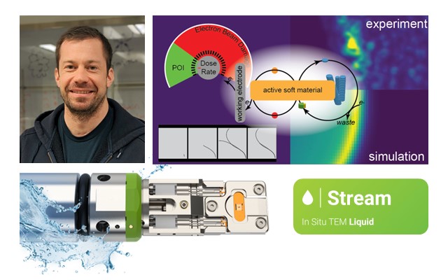
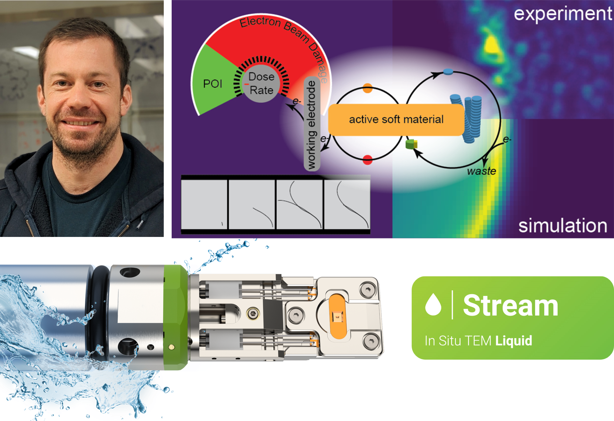
In a recent study published in the renowned journal of ACS Nano, a team of researchers from the University of California (UC) Irvine and the University of Massachusetts Boston employed the DENSsolutions Stream system to investigate the dynamics of electrochemically driven active materials. Impressively, they were able to capture single fiber dynamics at subsecond temporal resolution, as well as larger transitory fiber foci structures with nanoscale resolution. This research, involving our dear user at UC Irvine, Prof. Dr. Joe Patterson, is a major step forward in using electrochemical liquid EM to understand the dissipative self-assembly processes that generate active materials – a research space that remains largely unexplored. Notably, our Stream system played a vital role in enabling the visualization of these intricate electrochemical processes, providing key insights into the relationship between chemical kinetics and material dynamics.

Hierarchical evolution of fiber dynamics

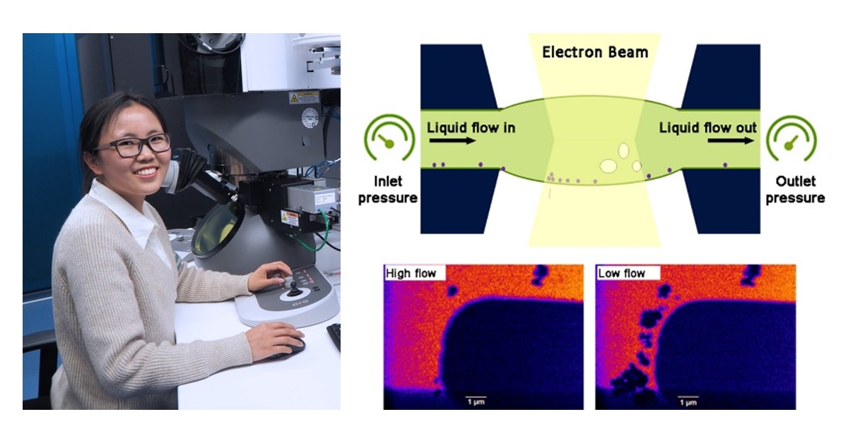
The nanoscale self-assembly processes observed in this study involve the electrochemical oxidation of a free cysteine thiol precursor (CSH) molecule to its disulfide gelator form (CSSC) using the ferricyanide/ferrocyanide redox couple as a electrochemical catalyst. For the experiments, Wyeth Gibson and his fellow collaborators utilized the Stream Nano-Cell’s working electrode as the anode, which provided the driving force for the oxidation of ferrocyanide to ferricyanide and the follow-up oxidation of CSH to CSSC. 

After capturing the dynamics of individual fibers under electrochemical stimulation near the electrode, the researchers were then able to capture the micrometer-scale hierarchical evolution of fiber clusters. As shown in the movie below, the fiber foci experience a maximum growth at 87 s and disassembly at 167 s. Evidently, the overall growth and shrinking of the fiber foci seem to loosely correspond with application and removal of electrochemical stimulus.

Movie 1: LPEM movie depicting the fiber foci growth and disassembly 

Capturing fiber foci modification

The next step for the researchers was to study the active material’s dynamics in response to further electrochemical stimulus. They applied a current to the structures and activated the electron beam, which was maintained at a constant throughout the experiment.  As shown in Movie 2 below, for the first 100 seconds, the fiber foci remained stable. At 100 s, a self-assembly growth front moved from left to right, causing the structures to grow and increase in contrast. At 200 s, a second growth front emerged as the first front reached the electrode boundary, spreading outward from the electrode in all directions. Between 400 and 600 seconds, the structures began to break down, shrink and decrease in contrast across the viewing window.

Movie 2: LPEM movie depicting the electrochemically driven fiber foci modification

Movie 3: LPEM movie depicting the fiber foci modification

Next, a regional segmentation analysis was performed in order to quantify the observed wave-like propagation of these self-assembly fronts. This is depicted in Movie 3, whereby the middle panel shows the segmented particles corresponding to the LPEM movie shown in the left panel. The graph in the video depicts the normalized change in segmented particle area over time for each region, with the segmented regions represented by blue (closest to the electrode), purple, red, and yellow (farthest from the electrode).

It is evident that the distance from the electrode affects the maximum structural density in a sequential manner. Notably, Dr. Gibson and his collaborators effectively demonstrate that the active material can be dynamically manipulated to form multiple growth fronts influenced by electrodes at different spatial locations.

Next, a regional segmentation analysis was performed in order to quantify the observed wave-like propagation of these self-assembly fronts. This is depicted in Movie 3, whereby the middle panel shows the segmented particles corresponding to the LPEM movie shown in the left panel. The graph in the video depicts the normalized change in segmented particle area over time for each region, with the segmented regions represented by blue (closest to the electrode), purple, red, and yellow (farthest from the electrode). It is evident that the distance from the electrode affects the maximum structural density in a sequential manner. Notably, Dr. Gibson and his collaborators effectively demonstrate that the active material can be dynamically manipulated to form multiple growth fronts influenced by electrodes at different spatial locations.

Movie 3: LPEM movie depicting the fiber foci modification

Integrating observations with simulations

To gain a clearer understanding and measure the structural transformation within the liquid cell, the researchers utilized structural dissimilarity (DSSIM) analysis on the electrochemical LPEM video. DSSIM analysis is a video processing technique that spatially and temporally quantifies structural changes occurring in a video. Importantly, by combining the LPEM data with kinetic simulations, they discovered that the formation of an active material can foster a local environment that boosts the pace of the self-assembly process, exhibiting an autocatalytic behavior.

Movie 4: DSSIM visualization and quantification of fiber foci dynamics

A pioneering electrochemistry study

Conclusively Prof. Dr. Joe Patterson and his fellow researchers performed a cutting-edge study, employing a combination of techniques including LPEM, electrochemical analysis, quantitative video analysis and kinetic simulations to explore a widely untapped research space – the self-assembly mechanisms in electrochemically fueled active materials. This innovative research highlights the crucial role of liquid electron microscopy in studying active materials, offering vital insights into the interplay between chemical kinetics and material behavior. We are certainly proud of the key role that our Stream system has played in bringing this research to fruition, and we look forward to the pioneering academic contributions that the Patterson Lab will continue to deliver.

“These were the most challenging liquid electron microscopy experiments I have ever performed, and the DENSsolutions Stream system was essential for getting them to work.”

Prof. Dr. Joe Patterson   Professor  |  University of California Irvine

Original article:


Discover our Stream solution:

Subscribe to our newsletter to stay up-to-date with the latest in situ microscopy news.

Breaking boundaries: Electrochemical impedance spectroscopy meets environmental TEM

Breaking boundaries: Electrochemical impedance spectroscopy meets environmental TEM

Employing the DENSsolutions Lightning system, researchers were able to apply a novel integrated EIS-ETEM approach to a common ceramic electrolyte, subjecting it to an array of stimuli, such as reactive gases, elevated temperatures and applied electrical potentials.

Original article by Ma et al.

Preparing and conducting high-temperature solid-state electrochemical TEM – particularly relevant to solid oxide fuel and electrolysis cells (SOFC and SOEC) – poses a number of challenges. These challenges include ensuring mechanical stability during chip mounting, preventing sample fracture or loss of electrical contact and minimizing unavoidable leak currents through the chip components. Despite its many challenges, the integration of electrical impedance spectroscopy and environmental TEM uniquely facilitates the direct correlation between electrochemical activity and the nanoscale structure and composition of materials. In a recent paper published in Small Methods – involving our dear user at the Technical University of Denmark (DTU), Dr. Søren Bredmose Simonsen – the DENSsolutions Lightning system was utilized to study micro gadolinia-doped ceria (CGO). The behavior of CGO, a ceramic electrolyte with various electrochemical properties, was investigated under a diverse range of stimuli, including reactive gasses (O₂ and H₂/H₂O), elevated temperatures (room temperature — 800 °C) and applied electrical potentials. Importantly, this research marks a significant advancement in materials science, pioneering the integration of EIS with in situ ETEM. 

CGO sample structure

Dr. Simonsen and his fellow collaborators meticulously designed the CGO sample for operando EIS-TEM investigations. A snapshot of the mounting process on the DENSsolutions Lightning Nano-Chip is shown in Figure 1b below. With a thin central part flanked by thick side parts, this sample configuration facilitates the separation of the contribution of bulk charge transport and the surface reaction processes. Notably, Dr. Simonsen emphasized the unique benefits of the Lightning Nano-Chip, highlighting its advantageous geometry. He explained, “The geometry of the DENSsolutions Lightning Nano-Chip is uniquely beneficial for our studies as it features a relatively long distance between the heater and the sample region. This allows us to mount and post-thin samples without the risk of creating pathways for leak current between the heater and sample or biasing electrodes.”

Figure 1: CGO sample mounted on a DENSsolutions Lightning Nano-Chip, visualized by SEM, TEM and HRTEM imaging.

EIS electrical circuit model

The researchers then explored the EIS spectra under three different gas environments at temperatures from 500 °C to 800 °C (see Figure 2 below). The Nyquist plots from EIS data reveal two distinct arcs, each representing different electrochemical processes. Through electrical circuit modeling, the contributions of resistances and capacitances are shown. Notably, the surface exchange reaction resistance exhibits a clear temperature dependence, reflecting thermally activated processes for both the transport and surface reaction.

Figure 2: EIS spectra (symbols) and fittings (lines) recorded in a) 3 mbar O₂ and in a H₂/H₂O with partial pressure ratio of b) 0.003 and c) 0.8; 10 kHz (square); 100 Hz (diamond), 1 Hz (circle), 0.1 Hz (triangle) are noted on the spectra, with hollow symbols.

Schematic illustration of CGO sample

In Figure 3 below, a schematic diagram of the differences for the CGO TEM sample in O₂ and H₂/H₂O is presented. Notably, in both O₂ and H₂/H₂O atmospheres, the conductivity and surface exchange reaction of CGO demonstrate notable dependencies on the gas environment. In the two scenarios, there are distinct chemical reaction formulas. In O₂, CGO predominantly conducts ions, confining the active surface near the Pt current collector. However, in the H₂/H₂O environment, electrons flow through CGO’s side parts, activating the entire surface.

Figure 3: Illustration of active surface area for Pt-CGO as a) pure ionic conductor and as b) mixed electronic/ionic conductor. Arrows indicate the direction of ions (red) and electrons (navy).

Electrochemical EIS meets TEM

The researchers then analyzed the transport and surface exchange resistance from the EIS measurements in each type of gas environment separately. Figure 4 below delves into the temperature and oxygen partial pressure (pO₂) dependence of CGO conductivity and surface exchange resistivity in different gas atmospheres. Notably, the conductivity in O₂ exhibits a characteristic temperature-dependent behavior, aligning closely with reference data for bulk polycrystalline CGO. Conversely, in H₂/H₂O environments, the conductivity shows a marked increase with decreasing oxygen partial pressure, indicative of a shift towards mixed electronic and ionic conduction. Moreover, the surface exchange resistance demonstrates a consistent decrease with increasing H₂/H₂O ratio, underscoring the influence of electronic charge carriers on electrochemical processes. 

Figure 4: Electrochemical EIS-TEM measurements of CGO in different atmospheres via Arrhenius plots.

A novel integration

Dr. Simonsen and his fellow collaborators performed a comprehensive in situ TEM heating and biasing study using the DENSsolutions Lightning system, elucidating the nuanced interplay between gas environment, temperature and material properties of micro gadolinia-doped ceria, a common ceramic electrolyte. This innovative research taps into new academic frontiers by combining electrochemical impedance spectroscopy with in situ environmental transmission electron microscopy investigations. Importantly, the developed EIS-TEM platform in this study is an important tool in promoting the understanding of nanoscale processes for green energy technologies, such as solid oxide electrolysis/fuel cells, batteries, thermoelectric devices and many more. 

“The geometry of the DENSsolutions Lightning Nano-Chip is uniquely beneficial for our studies as it features a relatively long distance between the heater and the sample region. This allows us to mount and post-thin samples without the risk of creating pathways for leak current between the heater and sample or biasing electrodes. Moreover, if not for the Lightning system’s low internal capacitance and high resistance, it would not have been possible to conduct electrochemical measurements for our materials.”

Dr. Søren Bredmose Simonsen   Senior Research  |  Technical University Denmark

Original article:


Discover our Lightning solution:

Discover more publications made possible by Lightning:

Thomas article feature image

Lightning system helps uncover the interaction mechanism in reactive metal-ceramic system, Al-SiC

The DENSsolutions Lightning system was utilized to reveal the evolution mechanism of the Al–AOL–SiC system under heating and biasing conditions and under an ultrahigh resolution of 4 Å.

Subscribe to our newsletter to stay up-to-date with the latest in situ microscopy news.

Liquid flow control: Unlock untapped research capabilities within in situ LPEM

Liquid flow control: Unlock untapped research capabilities within in situ LPEM

Via the unique on-chip microfluidic channel of the DENSsolutions Stream system, researchers were able to create a highly controlled chemical environment for visualizing the nanoscale metallic electrodeposition of copper crystals.

Original article by Cheng et al.

Liquid phase transmission electron microscopy (LPTEM) enables the observation of time-resolved dynamics in liquid state at high spatial resolution. The technique has gained exponential popularity over the last decade, and has contributed greatly to a wide range of fields, including materials science, chemistry and life science. With LPEM, researchers can explore the dynamical evolution of key materials and uncover fundamental insights into nucleation and growth. Only in recent years have researchers been able to control the chemical environment within an in situ LPEM experiment, owing to the award-winning innovation that is the DENSsolutions Stream system. In a recent publication, researchers including Dr. Ningyan Cheng from Anhui University utilized the Stream system to visualize the metallic electrodeposition of copper crystals in a highly controlled chemical environment. This was made possible due to the unique on-chip flow channel of Stream, which enables numerous advantages such as the ability to flush away beam-induced species, explore flow-dependent liquid dynamics and easily change electrolyte composition.

On-chip microfluidic channel

The core of the DENSsolutions Stream system is our patented Nano-Cell, which consists of a top and bottom chip, together forming a sealed compartment that enables users to safely perform liquid experiments inside the TEM. The bottom chip contains spacers, an integrated liquid inlet, flow channel and an outlet. Via pressure-based pumps, a liquid sample can be driven from the inlet through the field of view and then through the outlet. This process is demonstrated in the video below. Importantly, users can independently control the pressure at the inlet and outlet of the Nano-Cell, and therefore the absolute pressure in the microfluidic channel. This then enables full control over the liquid flow rate within the cell.

Movie 1: Animation depicting the microfluidic channel of the Stream Nano-Cell

Efficient liquid flow

Before observing any liquid phenomena in the TEM, Dr. Cheng and her fellow collaborators first had to ensure that the flow was efficient and well-controlled. To do this, the researchers first assembled a dry Nano-Cell. The flow was then initiated by turning on the pressure-based pump, while keeping all imaging parameters constant. After 30 seconds, the imaging contrast changed abruptly, implying that the liquid had definitely flowed into the Nano-Cell. This process is shown in the video below. The time taken to completely fill the Nano-Cell ranges anywhere from tens of seconds to just 3 minutes when a flow rate of 8 μl/min is applied.

Movie 2: In situ TEM movie showing the liquid flow into the Nano-Cell in just 30 seconds

Removal of beam-induced species

A key benefit of controlling the liquid flow within an LPEM experiment is the ability to remove beam-induced particles. The researchers first generated particles by increasing the electron flux on purpose through changing the spot size from 5 to 1. The process of removing the beam-induced species in this experiment is detailed in the video below, with the direction of the flow going from top to bottom. As soon as the flow was cut off at 6.4s, the particles started to form and grow on the membrane. The flow was then switched on again at 11.7 seconds, which is when the particles that were stuck to the membrane started to peel off and move from the top to the bottom area in the field of view. It took just 2 minutes to fully flush away the particles, which is a reproducible process. The direction of the particles’ movement is the same as the direction of the flow (top to bottom), confirming the effectiveness and power of the liquid flow control. 

Movie 3: Removal of beam-induced species via liquid flow control

Capturing flow-dependent liquid dynamics

The next step for the researchers was to explore the effect of the flow rate on the electrochemical copper crystallization and dissolution processes in real time. They first observed the effect of using a higher flow rate of 1.4 μl/min on the Cu deposition and dissolution processes, which showed to be reversible. The protocol included the initial electrode cleaning, deposition (−0.9 V, 10 s), dissolution (+0.4 V, 15 s) and repeating the process for 4 cycles. As demonstrated in the video below, the researchers found that uniform copper deposition can be obtained at a higher liquid flow rate (~1.4 μl/min), whereas at a lower liquid flow rate (0.1 μl/min), the growth of copper dendrites was observed. 

Movie 4: Copper electrodeposition at a flow rate of 1.4 μl/min (left) and 0.1 μl/min (right)

Changing electrolyte composition

Besides exploring the effects of altering the flow rate, a major point of interest in this study was observing the effect of adding foreign ions, such as phosphates, on the electrodeposition. Such additives can affect the electrochemically deposited crystals by, for example, changing the nuclei structures. The researchers first studied the electrodeposition of copper from a pure CuSO₄ aqueous solution. In this case, no obvious dendritic morphology was observed and instead only granules were formed (see below Figure 1, Left).

After the experiment, the electrolyte in the sample source was replaced by a mixture of CuSO and KHPO solution. The liquid was kept flowing with a flow rate of 3 μl/min for 15 min, which enabled the researchers to directly study the electrolyte effect on the depositions in the same liquid cell by excluding all the uncertainties during different cell assembly. Contrastingly in this case, copper dendrites were observed to grow and the addition of HPO− ions in the electrolyte led to the formation of Cu-phosphate complexes (see Figure 1, Right). These results further confirm the importance of being able to modulate the electrolyte composition, and demonstrate the effectiveness of the environment control that Stream enables.

Figure 1: The effect of phosphate addition on Cu electrodeposition

Exploiting electrode design to alter the chemical environment

When studying Cu electrodeposition in the previous experiment, the researchers saw that dendrite formation can be further promoted by the in situ addition of foreign ions, such as phosphates. In order to confirm the generality of this technique, they also took a look at Zn electrodeposition in an aqueous solution of ZnSO. The figure below shows the total growth of the zinc layer at b) a lower potential of −0.9 V (versus Pt) in the first 10 seconds, and c) a higher potential of −1.1 V (versus Pt) in the next 10 seconds. In d) the total growth of the Zn depositions in the first 20 seconds is shown. The researchers observed in the first 10 seconds (−0.9 V) that the deposition on the inner edge is rougher compared to the outer edge. In the following growth at −1.1 V, dendritic depositions are nucleated and grown on the previous outer edge, while no further growth can be observed in the inner edge. This experiment demonstrates that the special electrode design of Stream enables the exploration of rich liquid dynamics within different chemical environments. 

Figure 2: Zinc electrodeposition in b) the first 10 seconds with a potential of −0.9 V and c) in the next 10 seconds with a potential of −1.1 V. d) shows the total Zn growth in the 20 seconds.

Conclusion

Through this study, it is shown that Stream’s distinctive ability to enable liquid flow control opens the doors for researchers to truly alter the chemical environment within the liquid cell. By controlling the liquid flow, a user can flush away beam-induced species, explore flow-dependent liquid dynamics and easily change electrolyte composition. Moreover, the unique design of the electrodes in the Stream system allows researchers to explore complex liquid dynamics within different chemical environments within the same liquid cell. Importantly, the direct observations made by Cheng et al. not only provide new insights into understanding the nucleation and growth, but also give guidelines for the design and synthesis of desired nanostructures for specific applications, such as high performance electrocatalysis for energy conversion and electrodes for secondary batteries. 

Hanglong Wu portrait

Image of Dr. Ningyan Cheng from Max-Planck-Institut für Eisenforschung GmbH

“The DENSsolutions Stream System not only provides a useful means to study a wide range of dynamics in solution, but also enables systematic studies of the effect of the chemical environment on the corresponding reactions through precise control of the flow rate, liquid composition and other significant parameters.” 

Prof. Dr. Ningyan Cheng   Associate Professor  |  Anhui University

Original article:

Discover our Stream solution:

Discover more publications made possible by Stream:

Thomas article feature image

Climate helps uncover phase coexistence and structural dynamics of redox metal catalysts

Using our Climate system, scientists are able to interrelate the atomic-scale structural dynamics of redox metal catalysts to their activity.

Subscribe to our newsletter to stay up-to-date with the latest in situ microscopy news.

The first direct observation of pharmaceutical non-classical crystallization

The first direct observation of pharmaceutical non-classical crystallization

Using the Ocean system, scientists achieve supersaturation in LPEM experiments, revolutionizing pharmaceutical crystallization


Original article by Jennifer Cookman, Victoria Hamilton, Simon Hall and Ursel Bangert

LPEM video showing the pre-crystallization process of flufenamic acid

Whereas classical crystallization deals with layer-by-layer growth of crystals, non-classical crystallization (NCC) involves multiple different crystallization pathways towards the formation of final stable crystals. Although NCC has been widely documented in research, there is still much to be explored regarding the intermediate stages of crystallization and their direct observation. This is especially true for small organic molecules like flufenamic acid (FFA), an anti-inflammatory drug used for the treatment of rheumatic disorders.

Using the DENSsolutions Ocean LPEM system, Dr. Jennifer Cookman from the Bernal Institute in the University of Limerick and her colleagues were able to capture the intermediate pre-crystalline stages of this small organic molecule. This research marks the first ever direct observation of a pharmaceutical material undergoing NCC, highlighting the rising value and importance of in-situ TEM techniques in the pharmaceutical industry. 

The observed processes of NCC

Crystallization is a fundamental process that occurs in nature to produce some of the most common materials in daily life, such as the popular active pharmaceutical ingredient (API) ibuprofen or FFA. Properties such as solubility and bioavailability are linked to the crystal structure of the active compound. Considering APIs are commonly polymorphic, it is important to understand the intermediate stages of their crystallization. Specifically, if we can identify polymorphs with more desirable properties in the intermediate stages of crystallization, then this opens the door to harnessing and potentially directing their formation.

In this study, Dr. Cookman and her colleagues observed in situ the processes involved in the nanoscale crystallization of FFA. As illustrated in the figure below, this process involves four stages: aggregation, coalescence into a metastable entity, nucleus formation, and finally, crystallization.

A summary of the observed processes involved in the nanoscale crystallization of FFA

The researchers observed that FFA begins as a collection of small independent pre-nucleation clusters (PNCs). These PNCs are essentially stable particle clusters that form prior to the nucleation of a solid phase. They were able to follow three notable aggregates of PNCs that each followed the same transformational events. Particularly, after aggregation, these PNCs each independently coalesced, or merged, and formed a metastable phase. After this, the densification and development of a nucleus occurs, leading to the formation of FFA crystals. The processes of coalescence and densification will be further discussed and depicted below.

Coalescence

The aggregation of the PNCs were shown to have occurred prior to the researchers’ initial observations. Therefore the primary transformation observed for the three aggregates was actually that of coalescence. In the image below, you can see clearly that for each of the three selected aggregates, the individual clusters merge to form one cohesive entity after approximately 3 minutes.

A time-lapse of each of the three aggregates of PNCs undergoing coalescence

Densification towards crystallization

Following coalescence is the densification and development of a nucleus. This nucleus is formed by the successive sacrifice of surrounding material, leading to the formation of a new crystalline-like object, significantly more electron dense than before. Whereas coalescence took around 3 minutes, this densification occurred rapidly in under 10 seconds. The image and three videos below depict this rapid pre-crystallization process of FFA. 

A frame-by-frame summary of the three aggregates illustrating the pre-crystallization process of FFA

Aggregate 1

Aggregate 2

Aggregate 3

Novelty in findings

This research contributes academically in that the direct observations reported for the crystallization of FFA reveal insightful new information about the potential pathways towards crystallization. Moreover, it highlights the need to further investigate the nucleation and resulting crystallization of other small organic molecules via in situ techniques such as LPEM. LPEM presents itself as a required and complementary tool to not only comprehend but also probe chemistry at the nanoscale. This is true especially in regards to the crystallization of pharmaceutical ingredients, in which the development of the end product highly depends on controlling at the molecular building block level. 

The novelty of this research also lies in that it sheds light on the crystallization and nucleation of pharmaceutical products, providing the necessary information to further refine industrial-scale processes. If we can observe and understand the crystallization pathways that small organic molecular crystals like FFA take, we can better streamline production activities and develop effective manufacturing processes for generic drugs. It is precisely our goal at DENSsolutions to enable researchers like Dr. Jennifer Cookman to continue to bridge gaps in research using our solutions and uncover results that can impact this world, in the pharmaceutical industry and beyond.  

DENSsolutions Jennifer Cookman

“The DENSsolutions Ocean holder is a simple solution to native environment metrology that has the potential to revolutionize how we view pharmaceutical crystallization.”


“The DENSsolutions Ocean holder is a simple solution to native environment metrology that has the potential to revolutionize how we view pharmaceutical crystallization.”

Dr. Jennifer Cookman
Post Doctoral Researcher | University of Limerick

Original article:


Discover our latest LPEM solution, Stream:

Discover more publications made possible by Ocean:

Do you want to receive great articles like this in your mailbox? Subscribe to our newsletter.

Achieving mass transport control with the award-winning Stream system

Achieving mass transport control with the award-winning Stream system

The on-chip flow channel of the Stream system allows for full control over pressure, flow rate, liquid thickness and electric potential

Original article by Anne France Beker, Hongyu Sun, Mathilde Lemang, Tijn van Omme, Ronald G. Spruit, Marien Bremmer, Shibabrata Basak and  H. Hugo Pérez Garza

The liquid phase transmission electron microscopy (LPTEM) community faces numerous challenges when performing in situ electrochemical studies inside the TEM. From a lack of control over the flow and liquid thickness, to limited experimental flexibility and reproducibility, these challenges have posed considerable limitations on research. As a result, DENSsolutions has developed an in situ LPTEM solution that addresses each and every one of these challenges – the Stream system. Due to its unique on-chip flow channel design, users can effectively control experimental conditions such as pressure, flow rate, liquid thickness, electrical potential and bubbles. STEM videos are shown below to demonstrate these advantages and visualize the in situ growth of copper with multiple morphologies.

Because you can independently control the pressure at the inlet and outlet of the Stream Nano-Cell, you can control the absolute pressure in the microfluidic channel. This state-of-the-art design consequently gives you full control over the flow and the bulging of the windows, and therefore the liquid thickness. As a result, spatial resolution is improved, enabling meaningful electron diffraction and elemental mapping in liquid. You can accurately define the mass transport and control the electric potential, granting you complete access to the full kinetics of the reaction.

The in situ LPEM study

In order to exhibit the benefits of the system, copper dendrites were grown and characterized in situ. After the electrodeposition of the copper, EELS and EDS characterization were performed with copper inside the viewing area. Furthermore, high resolution images and diffraction patterns of the grown copper dendrites were recorded using the TEM.

Removal of beam-induced species

A major issue when performing LPTEM experiments with an electrolyte is the undesired influence of the electron beam. In this experiment, the electron beam interacts with the copper electrolyte. However, because you can control the flow of the liquid, you can remove or flush away any unwanted beam-induced species from the region of interest (i.e. window, sample or electrodes). This is displayed in the STEM recording below with the flow moving from right to left.

STEM movie showing debris being flushed

Bubble dissolution

It is important in LPTEM to assure that the cell stays wet. However, when bubbles form, the cell starts to dry out. The Stream system was developed with this in mind, offering a solution to this challenge. Specifically, because you can control the absolute pressure in the microfluidic channel, you can remove unwanted gas bubbles by setting the pressure high. At higher pressures, the size of the bubble decreases until it disappears and vice versa. The dissolution of a bubble that was formed during this copper experiment is shown in the STEM video below.

STEM movie showing bubble dissolution

In situ growth of copper dendrites

The growth and stripping of copper was completed a few times via cyclic voltammetry. The cycles begin with copper reduction, corresponding to the growth of the copper dendrites. Next, oxidation takes place, corresponding to the copper dendrites being stripped. Interestingly, you can see in the STEM video below that after reduction, the dendrites are thicker whereas after oxidation, the dendrites become much thinner.

STEM movie showing 5 cycles of copper growth and etching

Liquid thickness control 

In order to perform high resolution imaging, it is important in LPTEM that the liquid thickness is kept low. Aside from high resolution imaging, controlling the liquid thickness is extremely important when performing analytical techniques like EDS, EELS and electron diffraction. Ideally, the liquid should be limited below the beam broadening, which is normally expected to happen around 500nm of liquid thickness. With this in mind, we designed our Nano-Cell such that the thickness stays below the beam broadening threshold based on the spacer thickness and the maximum bulging of the windows. In the figures below, the elemental mapping and electron diffraction of the electrodeposited copper are presented. 

Elemental mapping - Anne article

EDX elemental mapping showing the spatial distribution of b) the copper dendrites and c) the platinum electrode 

Electron diffraction Annette article

TEM image of the copper dendrites on the electrode in e) and the corresponding SAED patterns in liquid phase in f)

Complete flow control

Controlling the flow also has other important advantages that are expanding possibilities in research. Namely, the ability to manipulate the flow rate allows you to control the morphology. You can see in the STEM image below that when flow is applied, the copper grows in a continuous layer with more copper being deposited. On the other hand, without flow, the copper nuclei grow isolated. This is direct proof that the unique flow-control feature of the system allows you to control the kinetics of an electrochemical reaction.

Morphology of copper with and without flow using the Stream system

Conclusively, this research highlights the unique capabilities of the award-winning Stream system, proving its potential to enable and boost research in various application fields, ranging from battery research and fuel-cells to corrosion and electrocatalysis.

Original article:

More about Stream:

Do you want to receive great articles like this in your mailbox? Subscribe to our newsletter.