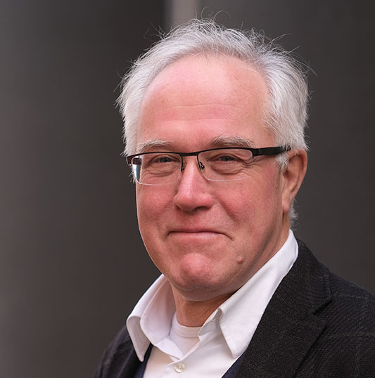
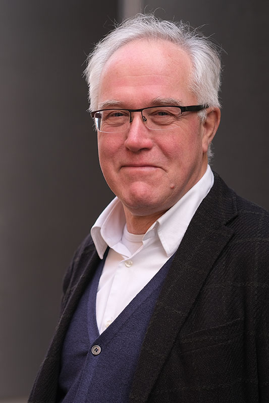
Meet our new Chief Commercial Officer (CCO) Robert Endert

In order to continue the growth of our company and further advance the field of in-situ TEM, it is important that we keep investing in our commercial activities. The current worldwide situation encourages us to find innovative online ways to build and strengthen relationships with our customers and distributors. For this we were looking for a Chief Commercial Officer (CCO) who could take our company to the next level.
With Robert Endert we have found the right man for the job. Next to being a great team player, he has a lot of experience in Electron Microscopy (EM), marketing and sales. Robert will focus on growing our business and further improving our relationships with customers and distributors. We asked him to introduce himself and provide some background information.
I graduated from Delft University of Technology in the research group Electron Optics. After this I joined Philips Electron Optics as an application specialist. Here I was involved in training and demonstration activities for customers from all over the world. Since developing user-interfaces was also part of my job I quickly realized that the user-friendliness of scientific equipment is a key factor for success.
In my next job I led the sales & service department for Philips Electron Optics in the Netherlands and Belgium; here I learned that customers are not just looking for topnotch specifications but also for adequate service and support.
In the years to follow I had a number of sales and general management functions in companies selling capital equipment and turnkey projects where sales cycles are long and funding processes are challenging.
Earlier this year I was contacted by the CEO of DENSsolutions, who I knew from my first job at Philips. He told me about the fast growing nano-science world and the important contribution of in-situ TEM to its progress. It didn’t take long before I got enthusiastic and agreed to join his team as CCO.
The world is facing many challenges that can only be solved by the contribution of scientists working on electron microscopic level. DENSsolutions is committed to support these activities with state-of-the-art in-situ MEMS technology.
I am a strong believer in teamwork and open and transparent communication to build long lasting relationships. Fortunately this has become a lot easier with modern communication means, opening up great possibilities to do online webinars and demonstrations.
That’s why I am really looking forward to being part of the DENSSolutions team and the exciting world of nano-science!
Thank you for reading, if you would like to know more about Robert, don’t hesitate to contact him: