Unraveling the dynamic behavior of zinc electrodes in aqueous electrolytes using our Stream system
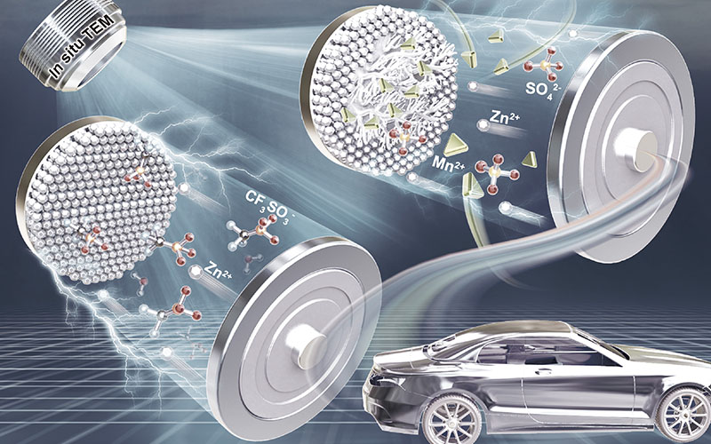
Scientists are able to observe for the first time using in situ TEM the morphology and phase evolution of zinc anodes during zinc dissolution and deposition in aqueous electrolytes.
Original article by Yongfeng Huang, Qingqing Gu, Zhanglong Guo, Wenbao Liu, Ziwen Chang, Yuefeng Liu, Feiyu Kang, Liubing Dong, Chengjun Xu
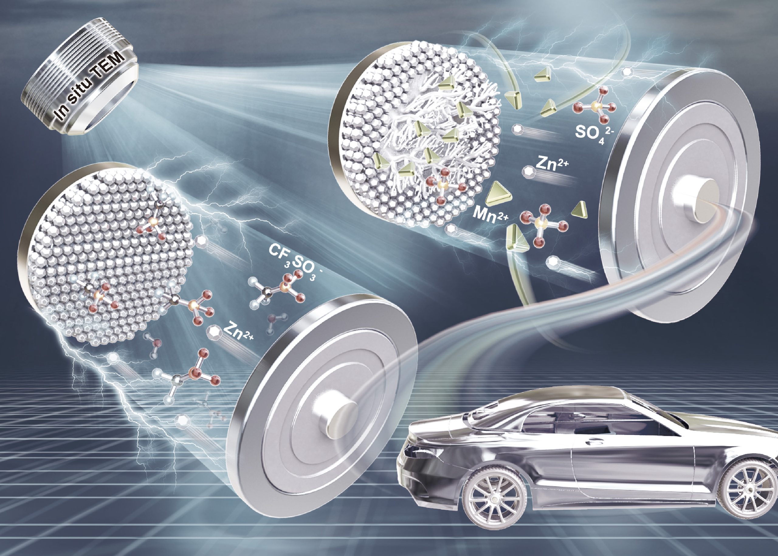
Metallic zinc is a widely used electrode material for aqueous rechargeable zinc-ion batteries (ZIBs) due to its high theoretical capacity, low redox potential, natural abundance and low cost. Despite these valuable benefits, zinc electrodes suffer from short cycling stability due to many factors such as the growth of zinc dendrites as well as corrosion. Little is known about the underlying reasons for the failure of zinc anodes on a deeper level. Indeed, the use of in situ transmission electron microscopy can serve as a means to bridge this gap in knowledge, unraveling the morphological evolution of zinc anodes during zinc dissolution and deposition in aqueous electrolytes.
In recent research performed at the DICP-DENS Microscopy Centre by Dr. Yuefeng Liu from the Dalian Institute of Chemical Physics, Yongfeng Huang from Tsinghua University, and many more collaborators, they were able to obtain a deep understanding of the stripping/plating behaviors of zinc in various aqueous electrolytes using the DENSsolutions Stream system. Specifically, the researchers investigated the effects of adding Mn²⁺ and CF₃SO₃⁻ in zinc-salt aqueous electrolytes on the zinc plating/stripping behavior. This work not only sheds light on the mechanism of zinc anodes during zinc dissolution/deposition processes in aqueous electrolytes, but also provides effective strategies to achieve long-term stable rechargeable zinc-ion batteries (ZIBs).
Three aqueous electrolytes
As the high reversibility of zinc anodes is a prerequisite for large- scale applications of ZIBs and ZHSs, many efforts have been dedicated to achieve long-term stable zinc anodes. One effective way to stabilize and acquire dendrite-free zinc anodes is by introducing additives in aqueous electrolytes. In previous studies, it was found that the addition of Mn²⁺ in the form of MnSO₄ to a ZnSO₄ aqueous electrolyte can actually suppress the dissolution of the MnO₂ cathode. Similarly, in comparison to a ZnSO₄ electrolyte, a Zn(CF₃SO₃)₂ electrolyte is far more effective in achieving better electrochemical performance of many ZIB systems.
For these reasons, aside from a pure ZnSO₄ electrolyte, ZnSO₄/MnSO₄ and Zn(CF₃SO₃)₂ are commonly used aqueous electrolytes for ZIBs. Despite this, zinc plating/stripping behaviors in ZnSO₄/MnSO₄ and Zn(CF₃SO₃)₂ and their effects on electrochemical stability of metallic zinc anodes are unknown. In this study, the researchers combine operando TEM and electrochemical analysis to unravel the zinc stripping/plating behaviors in the three aqueous electrolytes detailed above (ZnSO₄, ZnSO₄/MnSO₄ and Zn(CF₃SO₃)₂). In the following sections, in situ TEM images and videos of the zinc stripping/plating process in the three different electrolytes are shown.
1) Zinc plating/stripping process in a ZnSO₄ electrolyte
The researchers first constructed a micro zinc-ion battery inside the Stream holder, allowing them to monitor the zinc plating/stripping processes using the system’s on-chip flow channel. After assembling the Stream Nano-Cell and leak-testing it, the researchers were then able to flow the electrolytes into the liquid cell, using the pressure-based liquid pump to fully control the rate of the flow.
Next, the researchers set out to observe the zinc stripping/plating behavior in a pure ZnSO₄ aqueous solution. In Figure 1 below, the in situ TEM images detailing the zinc plating and stripping process at different times in 2 M ZnSO₄ are shown. During the zinc plating process exhibited in Figure 1a–d, the thickness of zinc deposited on the platinum substrate increases. Simultaneously, dendrite-like structures form and develop gradually. This confirms the dendrite issue of metallic zinc electrodes in the 2 M ZnSO₄ electrolyte, which leads to a short-circuit occurrence. After this, the zinc stripping process occurs, which is demonstrated in Figure 1d–f. During this process, it is observed that the deposited zinc is unable to fully strip away from the platinum substrate and dissolve into the electrolyte under the same charge and discharge time conditions. As a result, dead zinc is generated (see Figure 1f).
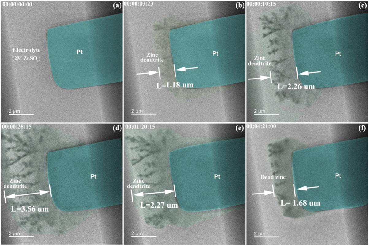
Figure 1: In-situ TEM images of zinc plating/stripping on the surface of Pt working electrode in 2 M ZnSO₄ electrolyte at different times: (a) 0 s, (b) 3 s, (c) 10 s, (d) 28 s, (e) 80 s and (f) 261 s.
Electrolytes of high concentrations are generally not conducive for monitoring zinc stripping/plating behaviors using in situ TEM, as they can block out the liquid inlet hole of the holder. Due to this, along with the valuable insights that further investigating the effect of concentration on dendrite growth can provide, the ZnSO₄ electrolyte was diluted from 2 M to 20 mM. The researchers then observed the zinc stripping/plating process in the 20 mM ZnSO₄ aqueous electrolyte. The in situ TEM images and corresponding movie detailing this process can be seen below in Figure 2 and Video 1, respectively.
The zinc stripping/plating process was controlled using the cyclic voltammetry (CV) technique at 20 mV/s. Figure 2g shows the corresponding CV curve, where the red dots marked as a–f correspond to the states in Figure 2a–f. At 71s (see Figure 2b), the researchers observed that the visible zinc particles in the electrolyte, as well as the dense dispositioned zinc and the zinc dendrites (marked in green) on the surface of the Pt substrate occur at the same. Between 76s–95s (Figure 2c-d), they noticed that more zinc was plating on the platinum surface, with the potential ranging from − 1.41 V to − 1.1 V. Next, the process of zinc dissolution occurs, where the zinc frontier line is observed to shrink back to area II at 114s (Figure 2e) and to the edge of the Pt substrate at 144s (Figure 2f). It is observed that the dendrite is still not completely removed when the potential returns to 0 V. Conclusively, although reducing the concentration can slow down dendrite formation, it does not fully suppress it.
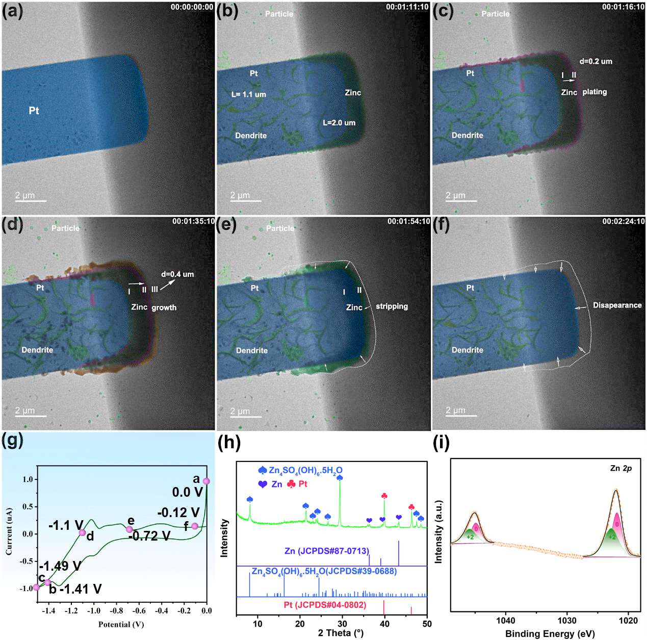
Figure 2: In-situ TEM images of zinc plating/stripping on the surface of Pt working electrode in 20 mM ZnSO₄ electrolyte at different times: (a) 0 s (b) 71 s, (c) 76 s, (d) 95 s, (e) 114 s and (f) 144 s. (g) CV curve of zinc stripping/plating process on the surface of Pt working electrode in 20 mM ZnSO4 electrolyte at a scan rate of 20 mV/s. (h) XRD pattern after zinc plating/stripping at Pt. (i) XPS result after zinc plating/stripping at Pt.
Video 1: Video of zinc plating/striping at the interface of Pt working electrode in 20 mM ZnSO₄ electrolyte.
2) Zinc plating/stripping process in a ZnSO₄/MnSO₄ electrolyte mixture
The next step for the researchers was to observe the zinc stripping/plating process in a ZnSO₄/MnSO₄ electrolyte mixture, as MnSO₄ additives in ZnSO₄ electrolytes can actually optimize the electro-chemical stability of metallic zinc electrodes. They first added 5 mM MnSO₄ to the 20 mM ZnSO₄ aqueous electrolyte. The in situ TEM images and corresponding movie detailing the resulting zinc plating/stripping process can be seen below in Figure 3 and Video 2, respectively.
Figure 3a–d depicts the zinc plating process, in which Mn spherical particles appear and gradually increase in size. At 124s (see Figure 3e), the zinc stripping process starts to occur, and these spherical particles in the electrolyte begin to disintegrate and finally disappear at 259s (see Figure 3i). Aside from the spherical particles in the electrolyte, a visible amount of deposited zinc (marked in green in Figure 3e) appears on the Pt working electrode. Notably, the sphere species, both in the electrolyte and also on the surface of the Pt substrate, disintegrate. This results in the further precipitation of zinc and leads to the increased thickness of zinc. Interestingly, zinc dendrites were not observed to form in the ZnSO₄/MnSO₄ electrolyte mixture, unlike in the pure ZnSO₄ electrolyte. This directly suggests that the Mn²⁺ additive is indeed beneficial for suppressing the formation of zinc dendrites.
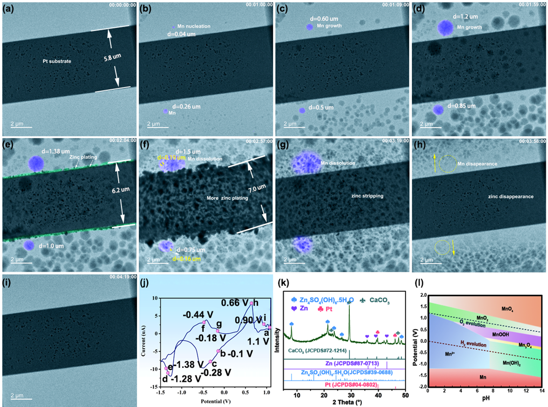
Figure 3: Zinc stripping/plating behaviors in 20 mM ZnSO₄ + 5 mM MnSO₄ electrolyte at different times: (a) 0 s (initial state), (b) 60 s (c) 69 s, (d) 119 s, (e) 124 s, (f) 177 s, (g) 199 s, (h) 238 s and (i) 259 s. (j) Cyclic voltammogram curve of Zn plating and striping at the interface of Pt working electrode at a scan rate of 20 mV/s, the red dots are assigned to Figure a-i, (k) XRD pattern after zinc plating/stripping at Pt (CaCO₃ is from the XRD bonding adhesives), and (l) E-pH diagram of Mn.
Video 2: Video of zinc plating/striping at the interface of Pt working electrode in the 20 mM ZnSO₄ + 5 mM MnSO₄ electrolyte.
3) Zinc plating/stripping process in a Zn(CF₃SO₃)₂ electrolyte
Finally, the researchers set out to explore the zinc plating/stripping process in a 20 mM Zn(CF₃SO₃)₂ electrolyte. The in situ TEM images and corresponding movie detailing the resulting zinc plating/stripping process in this electrolyte is shown in Figure 4 and Video 3, respectively. The zinc plating process is depicted in Figure 4a–d, where particle-like zinc uniformly deposits on the surface of the Pt substrate, and the thickness of the deposited zinc layer increases. Here, no zinc dendrites form during the plating process. At 175s (see Figure 4e), the zinc stripping process starts, and the deposited zinc particles on the Pt substrate gradually dissolve into electrolyte. Finally, at 240s (see Figure 4f), all zinc particles disappear, demonstrating the high reversibility of zinc deposition/dissolution in the Zn(CF₃SO₃)₂ electrolyte. Importantly, the deposition of zinc on the Pt substrate in the Zn(CF₃SO₃)₂ electrolyte is more uniform and homogeneous than that in the ZnSO₄ electrolyte and ZnSO₄/MnSO₄ electrolyte mixture.
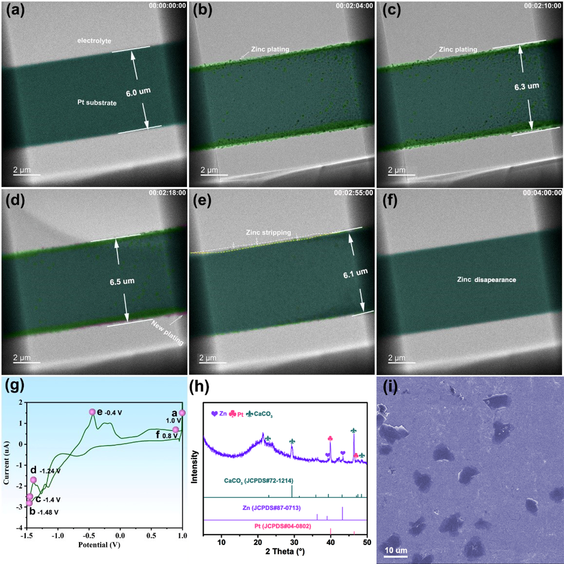
Figure 4: Zinc stripping/plating behaviors in 20 mM Zn(CF₃SO₃)₂ electrolyte at different times: (a) initial, 1.0 V (b) 124 s, -1.48 V, (c) 130 s, -1.40 V, (d) 138 s, -1.24 V, (e) 175 s, -0.40 V, (f) 240 s, 0.80 V, (g) Cyclic voltammogram curve at the scan rate of 20mV/s about Zn plating and striping at the interface of Pt working electrode in 20 mM Zn(CF₃SO₃)₂ electrolyte, the red dots are assigned to Figure a-f (h) XRD pattern after zinc plating/stripping at Pt (CaCO3 is from the XRD bonding adhesives). (i) SEM image after Zn plating on Pt.
Video 3: Video of zinc plating/striping at the interface of Pt working electrode in the 20 mM Zn(CF₃SO₃)₂ electrolyte.
Conclusion
This paper provides a novel understanding of the failure process of metallic zinc electrodes in a ZnSO₄ electrolyte, as well as the effects and acting mechanism of Mn²⁺ in the ZnSO₄/MnSO₄ electrolyte mixture and CF₃SO₃⁻ in the Zn(CF₃SO₃)₂ electrolyte on the zinc plating/stripping behavior. These deep-level insights serve to close the gap in our understanding of how we can create long-term stable ZIBs with metallic zinc anodes and optimal aqueous electrolytes, beneficial for several critical applications, including large-scale energy storage and portable electronic applications. The discovery of such findings could not be possible without the application of in situ characterization techniques, for which our Stream system has proved to be remarkably effective.
Original article:
Discover our Stream solution:
Discover more publications made possible by Stream:

Scientists develop a novel approach to generate extreme thermal gradients using our Wildfire Nano-Chip
Via a simple modification to our Wildfire Nano-Chip, scientists show that extreme thermal gradients across a TEM specimen can be generated.

