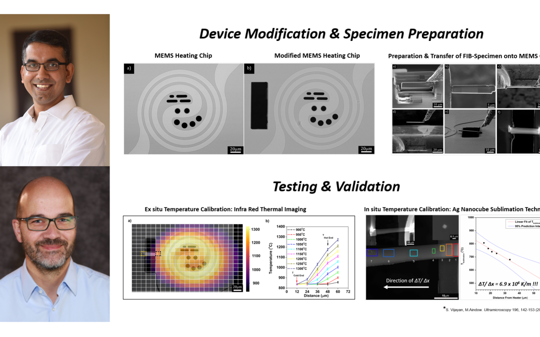
Scientists develop a novel approach to generate extreme thermal gradients using our Wildfire Nano-Chip
Via a simple modification to our Wildfire Nano-Chip, scientists show that extreme thermal gradients across a TEM specimen can be generated.
Original article by Sriram Vijayan, Rongxuan Wang, Zhenyu Kong and Joerg R. Jinschek

In traditional manufacturing processes, it is typically observed that the material experiences steady-state conditions. This results in the formation of stable equilibrium phases in the material. However, for those phases in materials that develop under ‘far-from equilibrium’ conditions, the same does not apply. In fact, for certain processing techniques that involve rapid thermal cycling and/or extreme thermal gradients, changes in the local phase equilibria, and therefore the local microstructure, often occur. Currently, observing these dynamic processes in materials under such conditions remains a great challenge. This is particularly because MEMS-based in situ TEM heating devices that can generate thermal gradients, combined with the capability to thermally cycle a specimen between different temperatures, are not currently available.
In recent research performed at The Ohio State University by Dr. Sriram Vijayan and Dr. Joerg Jinschek (now at Technical University of Denmark), as well as Rongxuan Wang and Dr. Zhenyu Kong from Virginia Tech, it is shown that controlled thermal gradients across a TEM specimen can be generated via a simple modification to our Wildfire Nano-Chip. Such a device can dramatically improve our understanding of material performance under extreme thermal conditions. Until now, thermally activated processes that affect microstructural stability of a material exposed to such thermal transients could only be investigated postmortem. Therefore, the need for new approaches to study thermally activated phenomena in materials in real time under such conditions is required. Importantly, this work is a major step forward in paving the way for scientists to be able to perform site-selective studies on materials under transient thermal conditions.
The study
As a first step, Dr. Vijayan and his fellow collaborators made modifications to a standard DENSsolutions Wildfire Nano-Chip. They then measured the local temperature distribution across the modified Nano-Chip and sample, and thereby the thermal gradient. The magnitude of the thermal gradient generated by this modified MEMS-based microheater was determined by measuring the temperature distribution using a combination of ex situ and in situ temperature measurement techniques. Regarding the ex situ temperature calibration, Dr. Vijayan and Dr. Jinschek teamed up with their MURI partners at Virginia Tech. As for the in situ temperature calibration, this was done at CEMAS, the state-of-the-art electron microscopy facility at The Ohio State University, using the previously established ‘Ag nanocube sublimation method’.
The Nano-Chip modification
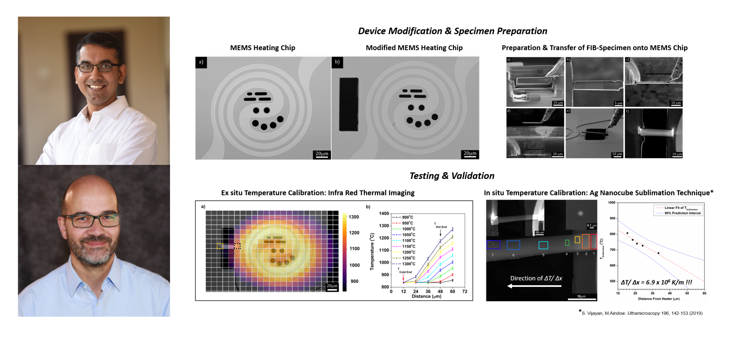
Using a Helios Nanolab 600 DualBeam focused ion beam (FIB)/scanning electron microscope (SEM), the researchers were able to modify a standard Nano-Chip. The Ga+ ion-based FIB was operated at an accelerating voltage of 30 kV and 6.4 nA beam current to mill a rectangular window next to the spiral metallic heater. This milled window can be seen in Figure 1b below. Importantly, after the FIB modification, the modified Nano-Chip exhibited no signs of deterioration in performance.

Figure 1: SEM images of the (a) unmodified Nano-Chip and (b) modified Nano-Chip.
Lamella preparation and transfer
Next, the researchers worked on preparing and transferring the FIB lamella from a (001) oriented single crystal silicon wafer surface onto the Nano-Chip. This workflow is detailed in Figure 2a–f below. The FIB-cut Si lamella was placed across the larger window (Figure 2e), with one end of the lamella on the heater and the other end on the SiN membrane acting as the heat sink. The Si lamella was welded to the MEMS heater using a Pt-based Gas Injection System (GIS) needle with the aid of the Ga ion beam. The Pt was welded at the top left edge and top right edge of the lamella as seen from the SE Image in Figure 2f.

Figure 2: Secondary electron (SE) and ion (SI) images of the FIB preparation and transfer of the lamella over the modified window in the FIB.
Ex situ temperature calibration
At Dr. Kong’s lab (Virginia Tech), the researchers then performed infrared thermal imaging (IRTI) experiments on the MEMS devices under ambient air conditions. IRTI is a particularly useful ex situ approach to measure the spatial distribution of temperature across the MEMS-device with a reasonable degree of accuracy. Using IRTI, the temperature distribution was measured across both the unmodified and modified Nano-Chip.
1) Temperature distribution across the unmodified Nano-Chip
First, the researchers measured the temperature distribution across the unmodified Nano-Chip to obtain reference temperature measurements. This distribution indicated that the metallic spiral heating element surrounding the viewing area of the microheater exhibited the highest temperature. Moreover, based on the temperature profile of the MEMS microheater, the spiral metallic heating element is the “hottest” region, while the surrounding SiN membrane is the “coldest” region on the MEMS device. These thermal conditions result in a large thermal gradient between the spiral metallic heater (= the “heat source”) and the SiN membrane (= the “heat sink”).
2) Temperature distribution across the modified Nano-Chip
In order to generate a thermal gradient across a specimen, a FIB-cut lamella must be placed such that one end of the specimen is on or adjacent to the heater and the other end is on the SiN membrane, away from the heater.
The researchers then performed IRTI again, but on the modified Nano-Chip with a FIB-cut lamella of Si placed across the modified window. As shown in Figure 3a below, the “hot end” of the Si lamella was adjacent to the outer spiral of the metallic heater, represented by the region enclosed in the black dotted square. On the other hand, the “cold end” was across the window in the SiN membrane, represented by the region enclosed in the yellow dotted square. Next, the thermal gradients across the FIB-cut TEM specimen were measured via an established technique that allows temperature measurement inside the TEM with high spatial resolution.

Figure 3: Overlay of the SEM image of the modified device with Si lamella on the thermal map of the device at 1300°C (unit of heatmap scale is in C), (b) the horizontal temperature line profile along the “hot end” (enclosed in dotted black square) and “cold end” (enclosed in dotted yellow square) of the Si lamella.
In situ temperature calibration
In order to validate the ex situ results and accurately measure the temperature across the FIB-cut specimen, the researchers measured the temperature via the established Ag nanocube (NC) sublimation method. The lamella was again placed such that the “hot end” was over the central spiral metallic heater and the “cold end” across the modified window. Next, monodispersed Ag NCs were dispersed onto the FIB lamella. The modified Nano-Chip was then heated to a set point temperature of 1,000°C and held until the Ag NCs completely sublimate. In Figure 4a below, the Ag NCs that dispersed across the FIB lamella are highlighted with colored boxes and labeled as regions 1–7. After sufficient sublimation events on the lamella were observed, the sublimation experiment was halted. Notably, the Ag NCs in region 6 and 7 did not completely sublimate, as the sublimation kinetics slowed down at lower temperatures.
“When exposing the FIB-cut TEM lamella to a combination of extreme thermal gradient heating and thermal cycling, the DENSsolutions Nano-Chip was observed to be extremely stable. The impulse software was very useful for these experiments as it allowed us to design complex temperature profiles during the heating experiments.” – Dr. Sriram Vijayan, Post-Doctoral Researcher, Center for Electron Microscopy & Analysis (CEMAS), The Ohio State University
The researchers then estimated the mean temperature of the Ag NCs on the FIB lamella found within regions 1–5. Subsequently, the mean temperatures obtained from regions 1 to 5 were plotted against the relative distance from the heater. In figure 4b below, a linear fit of the temperature data with 95% prediction intervals is presented. The thermal gradient of ΔT/Δx = 6.3 x 10⁶ °C/m was calculated at the temperature set point of 1,000°C.
The in situ results confirm that the researchers’ proposed modification of our Wildfire Nano-Chip has indeed generated a large thermal gradient across the FIB-cut TEM specimen. In fact, this resulting thermal gradient was found to be in the range of gradients observed in several engineering and manufacturing applications. Ultimately, this innovative approach now opens up the scope of research to address a wide range of material science problems observed under transient thermal conditions.

Figure 4: (a) SEM image of different regions (1–7) across the Si lamella where the temperature of the lamella was measured. (b) The linear fit of the temperature from the “hot end” to the “cold end” superimposed over the plot of the measured sublimation temp from region 1 to 5 versus distance from the “hot end”.
.
Conclusion
This paper presents a very simple methodology to study non-equilibrium processes in materials under extreme thermal gradients and rapid thermal cycling conditions. Specifically, this modified Nano-Chip can enable dynamic studies of the microstructural evolution in materials used in several critical applications, including nuclear reactor components, microelectronic packages and additively manufactured builds.
In the case of metal-based additive manufacturing (AM), extreme spatial and temporal thermal transients significantly impact the material microstructure within the melt pool and regions below the melt pool (‘previously melted’ layers of an AM build). Using this novel in situ TEM heating approach, we can now begin to observe and understand physical processes that contribute to the microstructural evolution in ‘previously melted’ layers during AM, thereby closing gaps in our understanding of processing-structure-property relationships in metal-based AM.
Ultimately, this powerful device can accurately simulate these complex thermal conditions inside the TEM and capture the microstructural evolution of materials during such extreme processing conditions. We are truly proud of the role that our Wildfire system has played in making this research possible and strive to continue enabling groundbreaking research now and in the future.

“Our modified DENSsolutions Wildfire Nano-Chip is well-suited for in-situ TEM heating experiments that require ‘far-from-equilibrium’ thermal conditions. This enables the observation of dynamic processes in a wide range of material systems at the nanoscale, which will further our fundamental understanding on microstructural stability of materials during processing and under ‘in-service’ conditions.”
Dr. Joerg Jinschek
Professor | Technical University of Denmark
Original article:
Discover our Wildfire solution:
Discover more publications made possible by Wildfire:

New measuring technique proves exceptional temperature accuracy of our Wildfire Nanochip
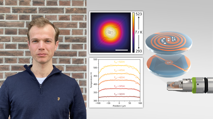
In collaboration with Utrecht University, we develop a novel technique to measure temperature at the nanoscale, showing the remarkable temperature accuracy and homogeneity of our Wildfire Nanochip.

